M
M
y
y
1
1
1
1
4
4
m
m
m
m
T
T
r
r
a
a
v
v
e
e
l
l
S
S
c
c
o
o
p
p
e
e
byCyrille de Brebisson
of Rhône-Alpes, France
During my last trip in the US, I was able to pick a 114mm/25.4mm primary/secondary mirror pair for 18$
(Telescope warehouse on eBay). After a lot of back and forth, I decided to make a travel telescope out of
it.
A travel scope is a telescope that is designed to be pulled apart and reassembled relatively rapidly and
that can therefore be used for trips (as its name indicates).
This article explains the design that I used what I learned and the things that I learned during the process.
Hopefully, it can serve as a warning to others!
The total cost for the scope (I had wood and nuts available to me), was around $40! Not bad!
Wanttomakeatravelscopebuttoolazytoreadthewholething?Readthis:
Play with this app:http://stellafane.org/tm/newt-web/newt-web.html
The top ring will need to have an inside diameter at least 25mm larger than the primary diameter to avoid
vignetting (dimensions will differ for larger/smaller mirrors). This will be the guiding factor for the rings
outside diameter.
Make ALL the rings the same size!
Use aluminum for the struts, wood is NOT rigid enough, trust me!
If you do not have a commercial spider, the easiest/simpler spider is the one that I used here. I tried 3
other designs and it is really the easiest to make.
Find a real focuser if you can. You lucky guys in the US can probably do good with a plumbing parts
focuser. Mine sucks!
Pay attention to the wood grain orientation. My telescope does not look “great” because I did not.
114mmTravelScope Page2of7
Uniqueissueswitha114mmtelescope.
114mm scopes are SMALL. This means that we have a lot of SMALL parts to make. Small parts are
harder to make (because you work closer to the blades), and because you need more precision.
114mm means a relatively light mirror. This means that the center of gravity of the tube will be further
away from the mirror than for larger scopes. As a result, the ‘down swing length’ of the bottom part of the
tube will be longer (as a percentage at least). So we will need a ‘taller’ base.
Information on tools and material can be found at the bottom of this document.
Variousnotes
IUsed10mmplywoodthroughout,but8mmcouldbeusedandwouldreducetheweight.
Resisttheurgetodrillalignedholesin2ormorepiecesofwoodatonce.Itisveryhardtobeperfectly
vertical,andevenifyouare,drillbitscanwander.Instead,makeatemplate(apaperdrawingwiththe
hole’scentermarked),andusea“pointythingy”tomarkthecenteronyourwoodthroughthepaper.
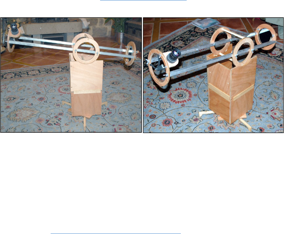
Part1:TheOpticalTube
The optical tube is an assembly of 4
rings, 2 struts, a mirror back, focuser
and spider.
You will need 4 rings of the SAME
outside diameter and if possible the
same inside diameter (although this
is not a must).
The outside diameter is at least the
primary diameter + 25mm + 2*strut
thickness (15mm in my case). You
can make it a little bit bigger to get
more rigid rings. For my scope, I
used a 175mm diameter.
You want the extra 25mm on the
diameter because you need to admit
light at a slight angle from the optical
axis. For an 800mm tube, an extra
12.5mm allows for an angle of 0.9
degree which corresponds to the so called 75% light area of the scope. It also probably helps if the optical
components are not 100% coaxial with the tube.
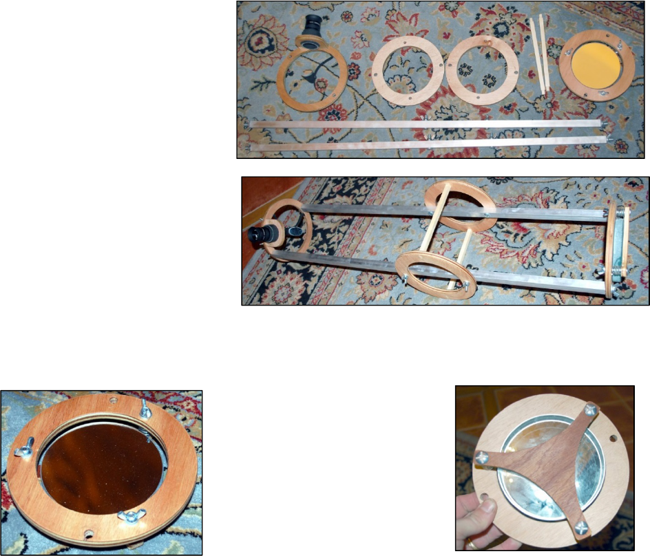
Step1:MirrorCell
The mirror cell has two main parts,
the ring (one of the four rings) and
the mirror back.
The mirror back has the same
diameter as the main rings. I made
mine triangular (prettier and lighter)
but it could be a circle. The mirror
back provides a platform for the
mirror that can be tilted in every
direction to align the optics. Once
114mmTravelScope Page3of7
the mirror back is cut, drill 3 holes in the 3 spokes (at the same distance from the center) and the
corresponding holes in the mirror ring. You are now ready to assemble them together. My springs had a
relatively large diameter, so I did not need washers for them, but I needed to stabilize them (so that they
would stay coaxial with the screws). I used a little bit of light foam. Once fitted, disassemble, put a coat of
finish on everything, let dry.
Glue the mirror to the mirror back; put 3 dabs of silicone and place the mirror on it (centered), press just a
little bit (being careful with the mirror), but not too much, you want to leave enough height of silicone to let
its own elasticity absorb any wood movement, but not so much that it will sag when lifting the mirror
horizontally. Protect if possible (place a card box on top) and let dry overnight.
Reassemble the mirror cell, put some pressure on the springs, BUT NOT TOO MUCH, we should be at
"resting/middle" position now, leaving adjustment in both directions on all 3 springs. Make sure that there
is enough force to avoid movement of the mirror under its own weight when moving from horizontal to
vertical. Set aside. Have a drink.
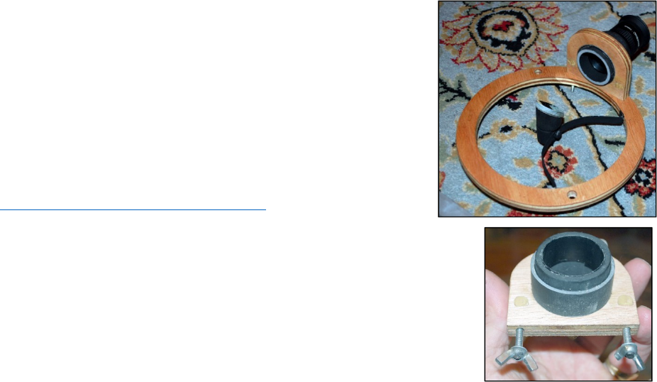
Step 2: Focuser Ring and Spider
You will need to mount the spider and the focuser on this ring. I
tried 3 different spider designs before going for this one. The issue
is that the smaller the scope, the smaller the parts, and the
HARDER it gets to make it! The design used here is honestly the
simplest to make! so, if you are not going commercial, I suggest
that you use it. The “Hub” is built out of a dowel slightly smaller
than 25.4 diameter (my secondary is 1”) with a center threaded
hole of 6mm. The mirror part is cut at 45°. I then made a vertical
cut in the hub part, used that as a base to drill a vertical hole large
enough to let the head of a 4mm bolt go through (it has to go just
pass the threaded hole, but have enough material on the other side
to not go through). The design is from
http://stellafane.org/tm/dob/ota/holder.html
The main thing to understand in this design is that the metal needs to be
rigid enough to not bend under its weight or telescope movements, BUT
needs to be flexible enough so that you can bend it to collimate the scope.
Hack saw blades are NOT OK as they are too rigid. I used a 1cm high strip
of tin (cut on the table saw, by sandwiching a piece of tin between 2
boards and using a blade that I only use for metal). For a larger scope with
a larger secondary, you might need something more rigid.
Paint it all in mat black.
Once you have the spider ready, you need to work on the focuser area. I
used a simple wood piece with a hole just big enough to allow me to force
a PVC tube in it, with a secondary tube sliding in it for focusing. I painted the whole thing mat black and
added some strips of electric tape to reduce the diameter to get the right friction.
I attached it to the focuser ring with 2 handmade wing bolts which screw in a washer/nut which I have
sealed (with wood putty) in the focuser. You can see the wood putty in the picture above, hiding the
nuts/washers.
The focuser will be the first thing fixed on the ring. You want to make its axis intersect the ring axis. The
best way to do that is to center the focuser hole in the focuser block and to make the 2 outer corners of
the focuser tangent the outside diameter of the ring. Make sure that the focuser is placed at around
35°~45° angle compared with what will be the horizontal of your optical tube.
Now, you can see where to place your spider. It should be held with 2 small 3mm wood screws, but do
not fix it yet.
114mmTravelScope Page4of7
Step 3: Struts
Assemble (temporarily) the focuser board and the ring. Measure the focuser center to ring distance. Also
measure the primary mirror surface to the top of the mirror cell ring.
Take your mirror focal length, subtract half of the internal diameter of the focuser ring, subtract the
focuser height (make it at least 60mm), subtract the distance from primary mirror to mirror cell ring top
and ADD the focuser ring to focuser center distance. This is your strut length. Cut the aluminum bars to
the right length (I use a regular 24 tooth 7-1/4” blade that I only use for metal on the table saw for this).
You will now need to fix the 8mm (6mm might be enough) bolts IN the struts. My bolts were slightly too
large, so I had to grind them. Once in, I fixed them in place using aluminum 2-part epoxy putty. Make sure
that they are as concentric as possible. Let harden.
Step 4. Drill Rings
You will need to drill all 4 rings in the same way and the same spot. See note above about drilling holes.
The hole in the focuser and mirror rings will be used for the struts, the holes in the 2 other rings will be
used for storage. Drill 8 holes.
Pay attention to the placement of the holes on the focuser ring to place the focuser where you want it.
You can also try to make it pretty by making sure that the holes are placed in the orientation of the wood
grain (Note that if you use my design with the spacer for the side rings, they will be assembled at 90°
angle compared with the 2 other rings).
The holes will need to be placed so that the outside of the struts are tangent to the outside of the ring. For
me, this meant at 15mm/2 = 7.5mm from the edge.
Make sure that ALL the holes in the rings (and pivot) are aligned so that you can stack them all in the box
and attach them all to avoid movement while traveling.
We will now locate the center of gravity of the tube.
Assemble the focuser/mirror and struts. Place one of your “Average” weight eyepieces in the focuser (you
want to balance with a medium weight). Using a dowel, or a long (but thin, <=1cm) piece of square wood
propped high enough to be at least half a ring diameter high, balance your assembly, note the balance
points on each struts and take the average distance. This corresponds to the center of gravity.
Now, for your side rings, you have two options. You can either use the holes that we have already drilled
and use them to bolt the side rings to the struts, OR you can (as I did) use these holes for spacers and
drill 4 other holes (2 per ring) to bolt the side rings to the struts. In this case, I suggest that you drill these
holes much closer to the inner diameter of the ring as it will clear more space on the outside of the rings
for bearing guides (see picture).
With all this together, you now should have an optical tube assembly! You can put it together, and, hand
held, go out and look at the moon! Rejoice in your work! First focusing might be hard….
114mmTravelScope Page5of7
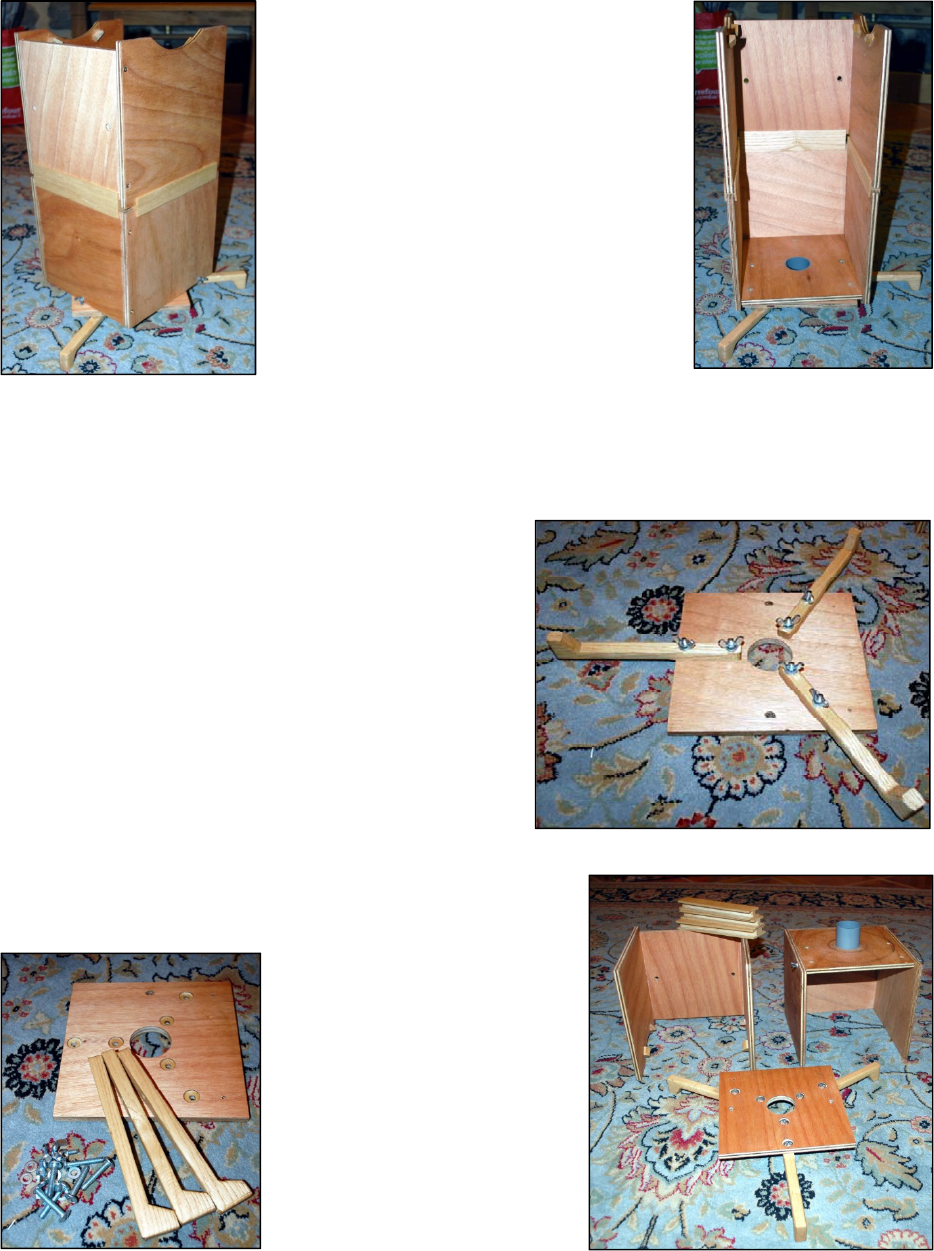
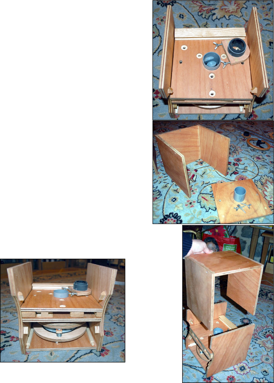
Part2:TheBase
In my case, I wanted the base to be also the
storage box, so I went for this two
interlocked U system.
I made the INSIDE of the box one ring
diameter + two ring thicknesses. This means
that the side rings rest on 4 small stops
glued on the INSIDE of the box. The side
walls of the box guide the rings (force them
to stay in the box), the spacers between the
2 side rings make sure that they do not bend
inward. The side of the box is cut in a circle
with a diameter slightly smaller than the
rings to guide them while letting the wing
nuts go by (hence the 4 hole per side ring,
with strut bolts closer to the interior diameter
design).
If I had to do it again, I would probably have the box 2 thickness smaller (in all dimension), reducing the
stored scope volume to 75%.
Because of distance between the side rings and the mirror I have to have at least 35cm from the top of
the base to the bottom of it. This is why I went for the 2U design. I can stack the 2 part of the box and get
a 40cm high base. I made three H-shaped wood ‘sticks’,
with friction fit, to connect the two parts of the box.
The bottom is made with two squares of same size, with a
piece of PVC used as the axis. This allows, when storing
everything to let the secondary protrude/stick up from the
focuser ring.
The part that attaches to the bottom of the U channel is
held by 3 wing bolts (same fabrication as for the focuser).
At the beginning, I tried to have 3 feet attached directly to
the bottom part of the base, but this did not provide a
large enough base and was unstable. So I changed the
design to the 3 detachable feet that you see in the final
design. See the countersink holes for the bolt heads in the
base to avoid friction. Felt is used as a bearing material
between the 2 plates. I used a PVC pipe as the axis. It is
forced in the top plate and loose fit on the 2
nd
. But, if I had
to do it again, I would use a threaded tube with a nut
under the rotating plate to reduce tilt.
114mmTravelScope Page6of7
StorageandTravel
The telescope can be disassembled and stored in the
box for travel. And there is enough space for eyepieces
in it also.
The telescope that can be assembled and collimated in
less than 10 minutes, weighs 2.5kg, it takes a space of
22 x 22 x 22cm plus the 2 struts, and has enough space
left to store all the accessories (I made a foam form that I
place in the top part for that)
Two holes in the box, aligned with the holes in the ring
allow for sandwiching of all the parts (using threaded
rods, not in the picture) for traveling.
I also drilled two small holes to fix the focuser to the
board to stop it from moving around. I place all the
hardware in a small plastic box coming from the local
pharmacy.
The latest changes (not shown here) are:
• 4 side bolts, similar to the ones used for the focuser
to close the box and a leather handle to carry it.
• A shroud (mat plastic, pinched from a file folder). I
tried holding it using scratch, but the scratch would
not glue to the wood, so I used blue tack at the end.
114mmTravelScope Page7of7
Thingslefttodo,orthatIwoulddodifferently:
I would pay more attention to wood grain to make it look nicer.
I would pay more attention to the focuser height. At this point in time, my focuser is only 25mm high due
to the fact that the focal length for far away object is not the same as the focal length for close ones…
I would get a bigger mirror ☺
I probably would make the ring ride on top of the box (not on the inside), to reduce the box size to 75% of
the current volume (20 x 20 x 20cm instead of 22 x 22 x 22cm). It makes quite a difference!
Material:
• 8 or 10mm plywood.
• 2 800mm or more aluminum squares tubes.
• 8mm, 6mm and 4mm bolts, washers and wing nuts.
• Small (3mm or smaller diameter) wood screws.
• Aluminum epoxy malleable compound (fix it type thing, like play dough, but hardens after 30 min or so)
• 3 relatively stiff springs in the 20mm range and at least 6mm inner diameter.
• PVC pipe in 45 and 35mm.
Tools:
Honestly, you need a table saw to build such an object. Base models retail for around $100. I suggest
that you purchase and mount on them a small (7-1/4”) thin blade with lots of teeth (40 or more, often
called plywood blades). Small/thin blades cut with less effort, tend to have a nicer finish on a low end
table saw. Also, make yourself a zero clearance plate. It will be a nice project to get acquainted with your
table saw. These will be necessary to cut some of the smaller parts of the travel scope.
Apart from that, usual tools (jig saw, drill, files, sanding paper…) will be needed.
• Saw to cut the plywood (table saw or bandsaw/jigsaw are best)
• Sanding material (power or not)
• A way to make circles is great also (lathe, circle jig on router...), but you can always hand cut them and
sand them round.
• A drill and drill bits for the various diameters that we use.
Published in January 2016
