
OWNERS’S MANUAL
Fusion
3
Table
Saw
36” & 52” Fence
LagunaTools.com

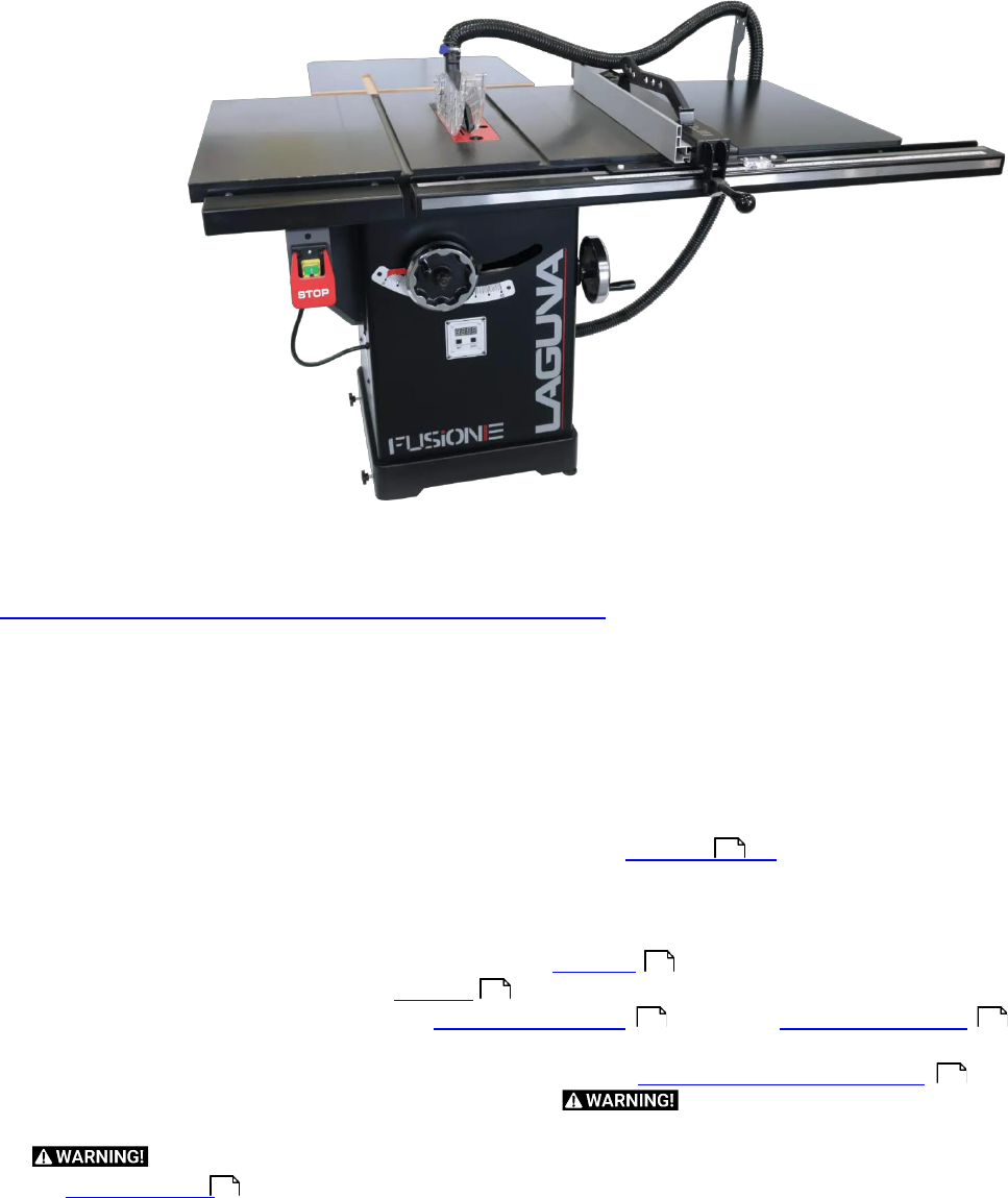
Thank you for investing in a Fusion Saw by Laguna Tools. This table saw is one of a family
of unique machines proudly offered by Laguna Tools. Every Laguna machine is engineered
for years of dependable service. Please feel free to contact Laguna Tools if you have a
question or suggestion. We appreciate working with you and your choice of a Laguna Tools
machine for your shop.
Regards,
Torben Helshoj
President & Founder Laguna Tools
Laguna takes pride in our products and stands behind them with continuing service and support for our customers. Your
Laguna machine was designed to bring a new dimension of productivity to your shop.
Before using your machine for the first time, learn how to use it. This manual covers a step-by-step process of assembly
and machine operation. If you have any questions, this manual will provide answers.
We do our best to thoroughly document every product that we sell for customer reference. Several files are compiled to
cover all components of a machine.
Several machines may be covered by one manual.
Many machines sold by Laguna include components with independent owners’ manuals.
The information contained in this publication was correct at the time of print. In the interest of continuous innovation, we
reserve the right to change specifications, design or included equipment without notice or obligation. No part of this
publication may be reproduced, transmitted, or translated into any language in any form by any means without our written
permission. Errors and omissions may be current.
Laguna Tools, Inc. LAGUNA® and the LAGUNA Logo® are the registered trademarks of Laguna Tools, Inc. All rights
reserved. 04/01/2019
LAGUNA AMERICAN HEADQUARTERS
Texas: 744 Refuge Way Suite 200, Grand Prairie, Texas 75050, U.S.A. Phone: +1-800-332-4094
Huntington Beach: 7291 Heil Ave Huntington Beach, CA 92647, U.S.A. Phone: +1-949-474-1200
South Carolina: 825 Bistline Dr. Ste 101, West Columbia, SC 29172, U.S.A. Phone: +1-800-234-1976
Minnesota: 5250 West 74th St, Edina, MN 55439, U.S.A Phone: +1-949-474-1200
lagunatools.com
supermaxtools.com
lagunacleanair.com
lagunalathe.com
LAGUNA
EUROPE
Walker Rd, Bardon Hill, Coalville LE67 1TU, United Kingdom. Phone: +44-1530-516921
lagunatools.uk
DAKE
CORPORATION
724 Robbins Road, Grand Haven, MI 49417, United States +1-800-937-3253
dakecorp.com
Fusion 3 Table Saw
© 2020 Laguna Tools
Table
of
Contents
Safety
......................................................................................
4
Electrical Saftey .......................................................................
9
Safety (FRENCH) .................................................................. 13
Setup
.................................................................................... 16
Inventory
List
.................................................................. 17
Unboxing
........................................................................ 21
Front
Rail
........................................................................
24
Rear
Rail ......................................................................... 28
Right Extension Table ..................................................... 32
Rear
Extension
Table
...................................................... 34
Front Rail Pt. 2 & Control Switch ......................................
37
Accessory
Installation
.................................................... 41
Maintenance
......................................................................... 49
Troubleshooting
.................................................................... 52
Specifications
....................................................................... 53
Wiring
Diagram
..................................................................... 59
Parts Diagram........................................................................
60
Parts List................................................................................ 65
Warranty
............................................................................... 76
Fusion 3 Table Saw \ Safety \
4
© 2020 Laguna Tools
Safety
Read and understand all warnings and operation instructions before using any tool or equipment. Always follow basic
safety precautions to reduce the risk of personal injury. Improper operation, maintenance or modification of tools or
equipment could result in serious injury and property damage. There are certain applications for which tools and equipment
are designed. This product should NOT be modified and/or used for any application other than for which it was designed.
It is important for you to read and understand this manual. The information it contains relates to protecting your safety and
preventing problems.
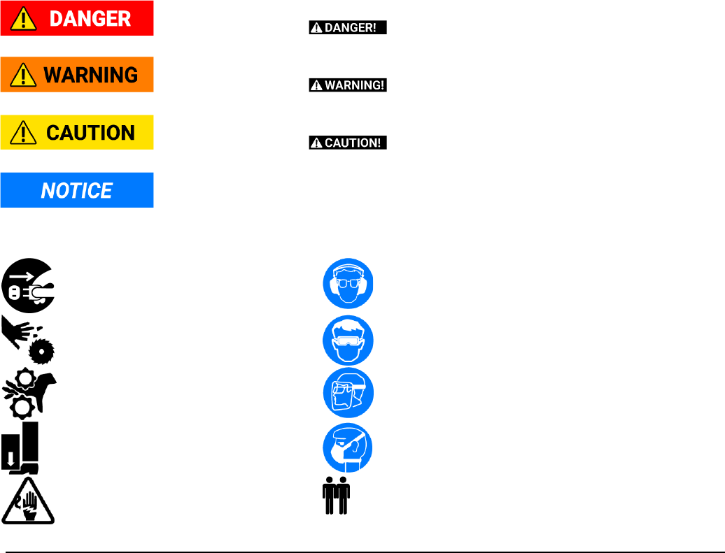
Safety Guidelines - Definitions
This manual contains information this is vital to protecting your safety and preventing equipment problems. To help you
recognize this information, we use the symbols below. Please read the manual and pay attention to these sections.
Safety
Call-outs
An imminently hazardous situation which, if not avoided, will result in death or serious injury.
Sometimes displayed as
A potentially hazardous situation which, if not avoided, could result in death or serious injury.
Sometimes displayed as
A potentially hazardous situation which, if not avoided, may result in minor or moderate injury.
Sometimes displayed as
A helpful tip from our technical staff. Sometimes displayed as NOTICE!
Safety
Symbols
Disconnect from power before proceeding.
Wear
ear
protection.
Be aware of possible laceration danger.
Wear Eye Protection.
Be aware of possible crushing danger. Wear a full face shield.
Be aware of possible crushing danger. Wear lung protection.
Electrical
Hazard.
..
X
Requires
X
People
Fusion 3 Table Saw \ Safety \
© 2020 Laguna Tools
5
Important
Safety
Instructions
Read and understand all warnings and operating instructions before using this equipment.
Failure to follow all instructions listed below, may result in electric shock, fire, and/or serious personal injury or property
damage.
Woodworking can be dangerous if safe and proper operating procedures are not followed. As with all machinery, there are
certain hazards involved with the operation of the product. Using the machine with respect and caution will considerably
lessen the possibility of personal injury. However, if normal safety precautions are overlooked or ignored, personal injury to
the operator may result. Safety equipment such as guards, push sticks, hold-downs, feather boards, goggles, dust masks
and hearing protection can reduce your potential for injury. But even the best guard won’t make up for poor judgment,
carelessness or inattention. Always use common sense and exercise caution in the workshop. If a procedure feels
dangerous, don’t try it. Figure out an alternative procedure that feels safer. REMEMBER: Your personal safety is your
responsibility.
This machine was designed for certain applications only. We strongly recommend that this machine not be modified
and/or used for any application other than that for which it was designed. If you have any questions relative to a particular
application, do not use the machine until you have first contacted the manufacturer to determine if it can or should be
performed on the product.
If you have any questions relative to its application do not use the product until you have contacted the manufacturer and
we have advised you.
General
Safety
Rules
FAILURE
TO
FOLLOW
THESE
RULES
MAY
RESULT
IN
SERIOUS
PERSONAL
INJURY.
FOR
YOUR
OWN
SAFETY,
READ
AND
UNDERSTAND
THE
INSTRUCTION
MANUAL
BEFORE
OPERATING
THE
MACHINE.
Learn the unit’s application and limitations as well as the specific hazards peculiar to it.
KEEP WORK AREA CLEAN. Cluttered areas and benches invite accidents.
DON’T USE IN DANGEROUS ENVIRONMENT. Don’t use this unit in damp or wet locations or expose it to rain. Keep work
area well-lighted.
KEEP CHILDREN AND VISITORS AWAY. All children and visitors should be kept a safe distance from work area.
DISCONNECT UNIT before servicing.
CHECK DAMAGED PARTS. Before further use of the unit, properly repair or replace any part that is damaged.
CSA
Required
Safety
Information:
Table
Saws
For Your Own Safety Read Instruction Manual before Operating Tablesaw.
a) Never place your hands in the vicinity or in line with the saw blade.
b) "Wear eye protection" or the sign M004 of ISO 7010.
c) Always use a properly functioning saw-blade guard, riving knife and anti-kickback device for every
operation for which it can be used, including all through sawing.
d) Use a push-stick or push-block when required.
e) Do not perform any operation freehand.
f)
Pay particular attention to instructions on reducing risk of kickback.
g) Never reach around or over saw blade.
h)
Turn off tool and wait for saw blade to stop before moving workpiece or changing settings.
i)
Never stand directly in line with the saw blade. Always position your body on the same side of the saw
blade as the fence.
In addition, use hearing protection and wear gloves when handling saw blades.

Fusion 3 Table Saw \ Safety \
6
© 2020 Laguna Tools
Guarding
Related
Warnings
a) Keep guards in place. Guards must be in working order and be properly mounted. A guard that
is loose, damaged, or is not functioning correctly must be repaired or replaced.
b)
Always use saw blade guard, riving knife and anti-kickback device for every through-cutting operation. For through-
cutting operations where the saw blade cuts completely through the thickness of the workpiece, the guard and other
safety devices help reduce the risk of injury.
c) Immediately reattach the guarding system after completing an operation (such as rabbeting, dadoing or resawing cuts)
which requires removal of the guard, riving knife and/or anti-kickback device. The guard, riving knife, and anti-kickback
device help to reduce the risk of injury.
d)
Make sure the saw blade is not contacting the guard, riving knife or the workpiece before the switch is turned on.
Inadvertent contact of these items with the saw blade could cause a hazardous condition.
e)
Adjust the riving knife as described in this instruction manual. Incorrect spacing, positioning and alignment can make
the riving knife ineffective in reducing the likelihood of kickback.
f)
For the riving knife and anti-kickback device to work, they must be engaged in the workpiece. The riving knife and anti-
kickback device are ineffective when cutting workpieces that are too short to be engaged with the riving knife and anti-
kickback device. Under these conditions a kickback cannot be prevented by the riving knife and antikickback device.
g)
Use the appropriate saw blade for the riving knife. For the riving knife to function properly, the saw blade diameter must
match the appropriate riving knife and the body of the saw blade must be thinner than the thickness of the riving knife
and the cutting width of the saw blade must be wider than the thickness of the riving knife.
Cutting
Procedures
Warnings
a) Never place your fingers or hands in the vicinity or in line with the saw blade. A
moment of inattention or a slip could direct your hand towards the saw blade and result in serious personal injury.
b)
Feed the workpiece into the saw blade or cutter only against the direction of rotation. Feeding the workpiece in the same
direction that the saw blade is rotating above the table may result in the workpiece, and your hand, being pulled into the
saw blade.
c) Never use the miter gauge to feed the workpiece when ripping and do not use the rip fence as a length stop when cross
cutting with the miter gauge. Guiding the workpiece with the rip fence and the miter gauge at the same time increases
the likelihood of saw blade binding and kickback.
d) When ripping, always apply the workpiece feeding force between the fence and the saw blade. Use a push stick when
the distance between the fence and the saw blade is less than 150 mm and use a push block when this distance is
less than 50 mm. "Work helping" devices will keep your hand at a safe distance from the saw blade.
e)
Use only the push stick provided by the manufacturer or constructed in accordance with the instructions. This push
stick provides sufficient distance of the hand from the saw blade.
f) Never use a damaged or cut push stick. A damaged push stick may break causing your hand to slip into the saw blade.
g)
Do not perform any operation "freehand". Always use either the rip fence or the miter gauge to position and guide the
workpiece. "Freehand" means using your hands to support or guide the workpiece, in lieu of a rip fence or miter gauge.
Freehand sawing leads to misalignment, binding and kickback.
h) Never reach around or over a rotating saw blade. Reaching for a workpiece may lead to accidental contact with the
moving saw blade.
i)
Provide auxiliary workpiece support to the rear and/or sides of the saw table for long and/or wide workpieces to keep
them level. A long and/or wide workpiece has a tendency to pivot on the table’s edge, causing loss of control, saw blade
binding and kickback.
j)
Feed workpiece at an even pace. Do not bend or twist the workpiece. If jamming occurs, turn the tool off immediately,
unplug the tool then clear the jam. Jamming the saw blade by the workpiece can cause kickback or stall the motor.
Fusion 3 Table Saw \ Safety \
© 2020 Laguna Tools
7
k)
Do not remove pieces of cut-off material while the saw is running. The material may become trapped between the
fence or inside the saw blade guard and the saw blade pulling your fingers into the saw blade. Turn the saw off and wait
until the saw blade stops before removing material.
l)
Use an auxiliary fence in contact with the tabletop when ripping workpieces less than 2 mm thick. A thin workpiece may
wedge under the rip fence and create a kickback.
Kickback Causes and Related Warnings
Statistics show that most common accidents among table saw users can be linked to kickback.
Kickback is a sudden reaction of the workpiece due to a pinched, jammed saw blade or misaligned line of cut in the
workpiece with respect to the saw blade or when a part of the workpiece binds between the saw blade and the rip fence or
other fixed object.
Most frequently during kickback, the workpiece is lifted from the table by the rear portion of the saw blade and is propelled
towards the operator.
Kickback is the result of saw misuse and/or incorrect operating procedures or conditions and can be avoided by taking
proper precautions as given below:
a)
Never stand directly in line with the saw blade. Always position your body on the same side of the saw
blade as the fence. Kickback may propel the workpiece at high velocity towards anyone standing in front and in line with
the saw blade.
b)
Never reach over or in back of the saw blade to pull or to support the workpiece. Accidental contact with
the saw blade may occur or kickback may drag your fingers into the saw blade.
c)
Never hold and press the workpiece that is being cut off against the rotating saw blade. Pressing the
workpiece being cut off against the saw blade will create a binding condition and kickback.
d)
Align the fence to be parallel with the saw blade. A misaligned fence will pinch the workpiece against the saw blade and
create kickback.
e) Use a feather-board to guide the workpiece against the table and fence when making non-through cuts such as
rabbeting, dadoing or resawing cuts. A feather-board helps to control the workpiece in the event of a kickback.
f) Use extra caution when making a cut into blind areas of assembled workpieces. The protruding saw blade may cut
objects that can cause kickback.
g) Support large panels to minimize the risk of saw blade pinching and kickback. Large panels tend to sag under their own
weight. Support(s) must be placed under all portions of the panel overhanging the table top.
h)
Use extra caution when cutting a workpiece that is twisted, knotted, warped or does not have a straight edge to guide it
with a miter gauge or along the fence. A warped, knotted, or twisted workpiece is unstable and causes misalignment of
the kerf with the saw blade, binding and kickback.
i) Never cut more than one workpiece, stacked vertically or horizontally. The saw blade could pick up one or more pieces
and cause kickback.
j)
When restarting the saw with the saw blade in the workpiece, center the saw blade in the kerf so that the saw teeth are
not engaged in the material. If the saw blade binds, it may lift up the workpiece and cause kickback when the saw is
restarted.
k) Keep saw blades clean, sharp, and with sufficient set. Never use warped saw blades or saw blades with cracked or
broken teeth. Sharp and properly set saw blades minimize binding, stalling and kickback.

Fusion 3 Table Saw \ Safety \
8
© 2020 Laguna Tools
Table
Saw
Operating
Procedure
Warnings
1.
Turn off the table saw and disconnect the power cord when removing the table insert,
changing the saw blade or making adjustments to the riving knife, anti-kickback device or saw blade guard, and when
the machine is left unattended. Precautionary measures will avoid accidents.
2.
Never leave the table saw running unattended. Turn it off and don’t leave the tool until it comes to a complete stop. An
unattended running saw is an uncontrolled hazard.
3.
Locate the table saw in a well-lit and level area where you can maintain good footing and balance. It should be installed
in an area that provides enough room to easily handle the size of your workpiece. Cramped, dark areas, and uneven,
slippery floors invite accidents.
4.
Frequently clean and remove sawdust from under the saw table and/or the dust collection device. Accumulated
sawdust is combustible and may self-ignite.
5.
The table saw must be secured. A table saw that is not properly secured may move or tip over.
6.
Remove tools, wood scraps, etc. from the table before the table saw is turned on. Distraction or a potential jam can be
dangerous.
7.
Always use saw blades with correct size and shape (diamond versus round) of arbor holes. Saw blades that do not
match the mounting hardware of the saw will run off-center, causing loss of control.
8.
Never use damaged or incorrect saw blade mounting means such as flanges, saw blade washers, bolts or nuts. These
mounting means were specially designed for your saw, for safe operation and optimum performance.
9.
Never stand on the table saw, do not use it as a stepping stool. Serious injury could occur if the tool is tipped or if the
cutting tool is accidentally contacted.
10.
Make sure that the saw blade is installed to rotate in the proper direction. Do not use grinding wheels, wire brushes, or
abrasive wheels on a table saw. Improper saw blade installation or use of accessories not recommended may cause
serious injury.
Fusion 3 Table Saw \ Electrical Safety \
© 2020 Laguna Tools
9
Electrical
Safety
Power
Connections
A separate electrical circuit should be used for your machines. This circuit should not be less than the wiring listed below
and should be protected with an appropriate circuit breaker based on the total running and start-up amperage's (listed
below). If an extension cord is used, use only 3-wire extension cords which have 3-prong grounding type plugs and
matching receptacle which will accept the machine’s plug.
Before connecting the machine to the power source, make sure the switch is in the “OFF”
position.
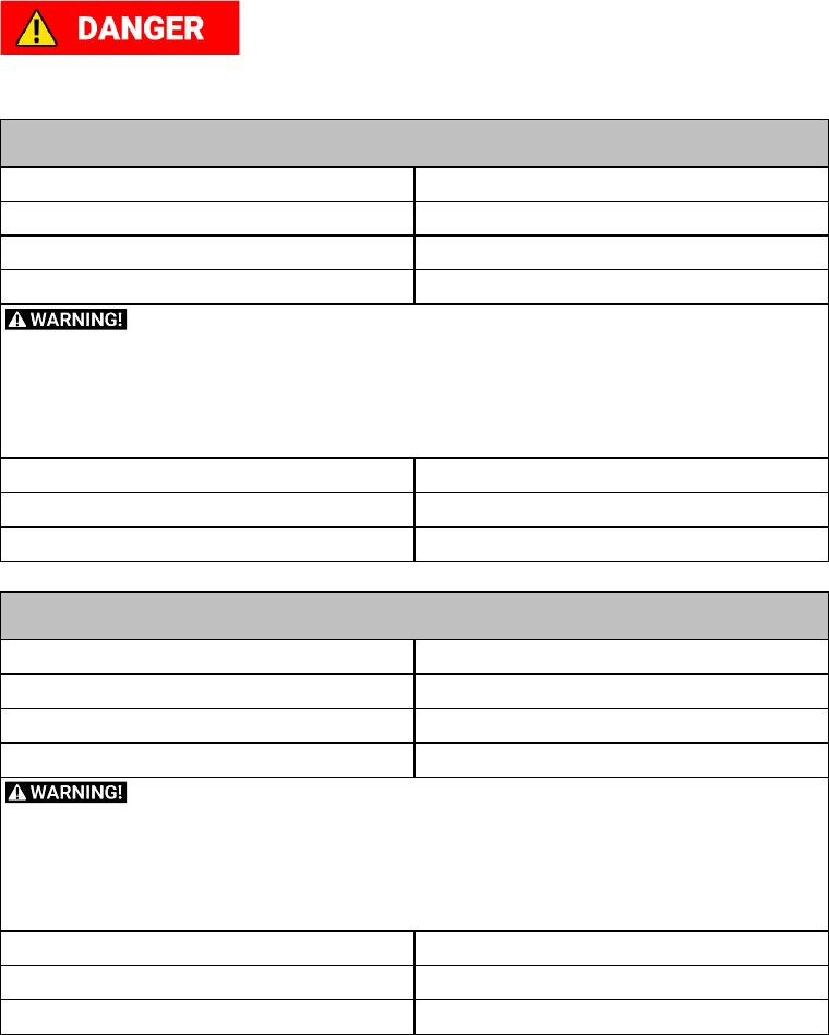
MTSF3362203-0130-36
VOLTAGE
220V
PHASE
1PH
HERTZ
60Hz
FULL LOAD AMPERAGE
14.8A
Below are RECOMMENDATIONS to be used for this machine based on the above
information. Variables outside of our control are:
Actual voltage supplied to the machine
Electrical code that must be met in your local province.
An
electrician
will
verify
that
all
the
demands
are
met
to
properly
wire
the
machine.
If
you
have
absolutely any doubt when wiring this machine - please consult with a qualified electrician.
PLUG/RECEPTACLE
6-15
WIRING (Gauge)
14 Ga. (minimum)
CIRCUIT BREAKER / (Fuse)
20AMP / (20 AMP Slow Blow)
MTSF3362203-0130-52
VOLTAGE
220V
PHASE
1PH
HERTZ
60Hz
FULL LOAD AMPERAGE
14.8A
Below are RECOMMENDATIONS to be used for this machine based on the above
information. Variables outside of our control are:
Actual voltage supplied to the machine
Electrical code that must be met in your local province.
An
electrician
will
verify
that
all
the
demands
are
met
to
properly
wire
the
machine.
If
you
have
absolutely any doubt when wiring this machine - please consult with a qualified electrician.
PLUG/RECEPTACLE
6-15
WIRING (Gauge)
14 Ga. (minimum)
CIRCUIT BREAKER / (Fuse)
20AMP / (20 AMP Slow Blow)

Fusion 3 Table Saw \ Electrical Safety \
10
© 2020 Laguna Tools
52
If this information is different than what is stated on the Motor Specification Plate - omit this
information. It is possible that the documentation is outdated to a machine change - such as a
different motor.
Always
check
the
motor
plate
prior
to any
wiring.
If
any
doubts, please consult a
certified electrician.
Know when to use a time delay fuse! AKA Slow blow fuse.
Generally, if the motor uses a start capacitor, a time delay fuse is required. This type of fuse
(circuit breaker) will not trip with the initial amperage needed to start the machine, which is typically double that of the
running amperage.
Most woodworking machines use this type of fuse.
Running on Low voltage will damage the machine. Never run the machine in wet or damp
conditions.
For a detailed wiring diagram please see the Wiring Diagram
section at the end of this
manual.
Fusion 3 Table Saw \ Electrical Safety \
© 2020 Laguna Tools
11
Grounding
Methods
This machine must be grounded while in use to protect the operator from electric shock.
In all cases, make certain that the receptacle in question is properly grounded. If you are not
sure, have a qualified electrician check the receptacle.
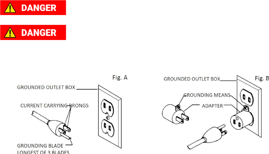
Grounding Methods Provided by CSA Group. (A) Receptacle with nominal rating less than 150 volts. (B) 150
volt receptacle without grounding pin fitted with adapter.
1.
All grounded, cord-connected machines:
In the event of a malfunction or breakdown, grounding provides a path of least resistance for electric current to reduce the
risk of electric shock. This machine is equipped with an electric cord having an equipment-grounding conductor and a
grounding plug. The plug must be plugged into a matching outlet that is properly installed and grounded in accordance with
all local codes and ordinances.
Do not modify the plug provided - if it will not fit the outlet, have the proper outlet installed by a qualified electrician.
Improper connection of the equipment-grounding conductor can result in risk of electric shock. The conductor with
insulation having an outer surface that is green with or without yellow stripes is the equipment-grounding conductor. If
repair or replacement of the electric cord or plug is necessary, do not connect the equipment-grounding conductor to a live
terminal.
Check with a qualified electrician or service personnel if the grounding instructions are not completely understood, or if in
doubt as to whether the machine is properly grounded.
Use only 3-wire extension cords that have 3-prong grounding type plugs and matching 3-conductor receptacles that accept
the machine’s plug, as shown in Fig. A. Repair or replace damaged or worn cord immediately.
2.
Grounded, cord-connected machines intended for use on a supply circuit having a nominal rating less than 150 volts:
If the machine is intended for use on a circuit that has an outlet that looks like the one illustrated in Fig. A, the machine will
have a grounding plug that looks like the plug illustrated in Fig. A. A temporary adapter, which looks like the adapter
illustrated in Fig. B, may be used to connect this plug to a matching 2-conductor receptacle as shown in Fig. B if a properly
grounded outlet is not available. The temporary adapter should be used only until a properly grounded outlet can be installed
by a qualified electrician. The green-colored rigid ear, lug, and the like, extending from the adapter is used, it must be held in
a place with a metal screw. NOTE: In Canada, the use of a temporary adapter is not permitted by the Canadian Electric
Code.

Fusion 3 Table Saw \ Electrical Safety \
12
© 2020 Laguna Tools
Extension
Cords
Use proper extension cords. Make sure your extension cord is in good condition and is a 3-wire extension cord
which has a 3-prong grounding type plug and matching receptacle which will accept the machine’s plug. When using an
extension cord, be sure to use one heavy enough to carry the current of the machine. An undersized cord will cause a drop
in line voltage, resulting in loss of power and overheating. Fig. D.1 or D.2, shows the correct gauge to use depending on the
cord length. If in doubt, use the next heavier gauge. The smaller the gauge number, the heavier the cord.
MINIMUM GAUGE EXTENSION CORD 120V
RECOMMENDED
SIZES
FOR
USE
WITH
STATIONARY
ELECTRIC
MACHINES
Ampere
Rating
Volts
Total Length of
Cord in Feet
Gauge of Extension
Cord
0-
6
0-
6
0-
6
0-
6
120
120
120
120
up to 25
25-
50
50-
100
100-
150
18 AWG
16 AWG
16 AWG
14 AWG
6-
10
6-
10
6-
10
6-
10
120
120
120
120
up to 25
25-
50
50-
100
100-
150
18 AWG
16 AWG
14 AWG
12 AWG
10-
12
10-
12
10-
12
10-
12
120
120
120
120
up to 25
25-
50
50-
100
100-
150
16 AWG
16 AWG
14 AWG
12 AWG
12-
16
12-
16
12-
16
120
120
120
up to 25
25-
50
14 AWG
12 AWG
GREATER THAN 50 FEET NOT
RECOMMENDED
MINIMUM GAUGE EXTENSION CORD 240V
RECOMMENDED
SIZES
FOR
USE
WITH
STATIONARY
ELECTRIC
MACHINES
Ampere
Rating
Volts
Total Length of
Cord in Feet
Gauge of Extension
Cord
0-
6
240
up to 50
18 AWG
0-
6
240
50-
100
16 AWG
0-
6
240
100-
200
16 AWG
0-
6
240
200-
300
14 AWG
6-
10
240
up to 50
18 AWG
6-
10
240
50-
100
16 AWG
6-
10
240
100-
200
14 AWG
6-
10
240
200-
300
12 AWG
10-
12
240
up to 50
16 AWG
10-
12
240
50-
100
16 AWG
10-
12
240
100-
200
14 AWG
10-
12
240
200-
300
12 AWG
12-
16
12-
16
12-
16
240
240
240
up to 50
50-
100
14 AWG
12 AWG
GREATER THAN 100 FEET NOT
RECOMMENDED
Fusion 3 Table Saw \ Safety (FRENCH) \
© 2020 Laguna Tools
13
Safety
(FRENCH)
AVERTISSEMENT!
Pour votre propre sécurité, lisez le manuel d'instructions avant d'utiliser la scie à table.
(a) DANGER - Ne placez jamais vos mains à proximité ou en ligne avec la lame de scie.
(b) AVERTISSEMENT - "Porter une protection oculaire" ou le signe M004 de la norme ISO 7010.
(c) AVERTISSEMENT - Toujours utiliser un protecteur de lame de scie, un couteau diviseur et un dispositif anti-retour pour
chaque opération pour laquelle il peut être utilisé, y compris tout au long du sciage.
(d) AVERTISSEMENT - Utiliser un bâton-poussoir ou un bloc-poussoir au besoin.
(e) AVERTISSEMENT - N'effectuez aucune opération à main levée.
(f) AVERTISSEMENT - Porter une attention particulière aux instructions sur la réduction du risque de rebond. (ou "Savoir
comment réduire les risques de pots-de-vin.")
(g) AVERTISSEMENT - Ne jamais tendre la main autour ou au-dessus de la lame de scie. (ou "Ne jamais tendre la main à
l'arrière ou au-dessus de la lame de scie").
(H) AVERTISSEMENT - Éteindre l'outil et attendre que la lame de scie s'arrête avant de déplacer la pièce ou de changer les
réglages.
(I) AVERTISSEMENT - Ne jamais se tenir directement en ligne avec la lame de scie. Placez toujours votre corps du même
côté de la lame de scie que la clôture.
De plus, utilisez une protection auditive et portez des gants pour manipuler les lames de scie.
Avertissements relatifs à la protection
Laisser les protecteurs en place. Les protecteurs doivent être en état de fonctionnement et montés correctement. Un
protecteur mal fixé, endommagé ou ne fonctionnant pas correctement doit être réparé ou remplacé.
Toujours utiliser un protecteur de lames, un couteau diviseur et un appareil antirecul pour toute opération de coupe
traversante. Pour les opérations de coupe traversante où la lame traverse complètement l'épaisseur de la pièce, le
protecteur et les autres appareils de sécurité contribuent à limiter le risque de blessure.
Fixer de nouveau immédiatement le protecteur après l'exécution d'une opération (telle que le refeuillement, l'engravure ou la
refente) qui nécessite l'enlèvement du protecteur, du couteau diviseur et/ou de l'appareil anti-recul. Le protecteur, le
couteau diviseur et l'appareil anti-recul contribuent à limiter le risque de blessure.
Veiller à ce que la lame n'entre pas en contact avec le protecteur, le couteau diviseur ou la pièce avant le déclenchement du
commutateur. Un contact involontaire de ces éléments avec la lame pourrait entraîner un fonctionnement dangereux.
Ajuster le couteau diviseur comme décrit dans la notice d'utilisation. Un espacement, un positionnement et un alignement
incorrects peuvent empêcher le couteau diviseur de limiter le risque de recul.
Pour que le couteau diviseur et l'appareil anti-recul fonctionnent, ils doivent être engagés dans la pièce. Le couteau diviseur
et l'appareil anti-recul sont inefficaces lorsque l'on coupe des pièces trop courtes pour que le couteau diviseur et l'appareil
antirecul puissent s'y engager. Dans ces conditions, le couteau diviseur et l'appareil anti-recul ne peuvent pas empêcher un
recul de se produire.
Utiliser la lame appropriée au couteau diviseur. Pour que le couteau diviseur fonctionne correctement, le diamètre de la
lame doit correspondre au couteau diviseur approprié, l'épaisseur de la lame de scie doit être plus mince que celle du
couteau diviseur et la largeur de coupe de la lame de scie doit être supérieure à l'épaisseur du couteau diviseur.
Avertissements relatifs aux modes opératoires de coupe
DANGER: Ne jamais mettre les doigts ou les mains à proximité ou dans l'alignement de la lame. Votre main pourrait glisser
ou se diriger vers la lame dans un moment d'inattention et entraîner une blessure grave.
Avancer la pièce en direction de la lame ou du couteau uniquement dans le sens inverse de rotation. L'avance de la pièce
dans le même sens que le sens de rotation de la lame au-dessus de la table peut entraîner la pièce et la main dans la lame.
Ne jamais utiliser le guide inclinable pour avancer la pièce lors d'un sciage en long et ne pas utiliser le guide longitudinal
comme butée longitudinale lors d'un sciage en travers à l'aide du guide inclinable. Le guidage de la pièce en utilisant en
même temps le guide longitudinal et le guide inclinable augmente le risque de blocage de la lame et de recul.
Fusion 3 Table Saw \ Safety (FRENCH) \
14
© 2020 Laguna Tools
Lors d'un sciage en long, toujours appliquer la force d'alimentation de la pièce entre le guide et la lame. Utiliser un poussoir
lorsque la distance entre le guide et la lame est inférieure à 150 mm et utiliser un bloc-poussoir lorsque cette distance est
inférieure à 50 mm. Des appareils d'aide à l'utilisation maintiendront la main à une distance sans risque de la lame.
Utiliser seulement le poussoir fourni par le fabricant ou construit conformément aux instructions. Ce poussoir permet de
garder une distance suffisante entre la main et la lame.
Ne jamais utiliser un poussoir endommagé ou coupé. Un poussoir endommagé peut faire glisser votre main dans la lame.
Ne jamais effectuer une opération "à main levée". Toujours utiliser le guide longitudinal ou le guide inclinable pour
positionner et guider la pièce. “A main levée" signifie utiliser ses mains pour soutenir ou guider la pièce, au lieu d'un guide
longitudinal ou inclinable. Une coupe à main levée entraîne un mauvais alignement, un blocage et un recul.
Ne jamais tendre le bras autour ou au-dessus de la lame rotative. Le fait d'étendre le bras pour atteindre une pièce peut
entraîner un contact accidentel avec la lame rotative.
Prévoir un support supplémentaire de la pièce à l'arrière et/ou sur les côtés de la scie circulaire pour des pièces longues
et/ou larges afin de les maintenir à plat. Une pièce longue et/ou large a tendance à pivoter sur le bord de la table, entraînant
une perte de contrôle, un blocage de la lame et un recul.
Avancer la pièce à un rythme régulier. Ne pas plier ou tordre la pièce. En cas de coincement de la lame, arrêter l'outil
immédiatement, le débrancher et décoincer la lame. Un coincement de la lame par la pièce peut provoquer un recul ou faire
caler le moteur.
Ne pas enlever des morceaux de matériau coupé lors du fonctionnement de la lame. Le matériau peut être emprisonné
entre le guide ou à l'intérieur du protecteur de lame et la lame, entraînant vos doigts dans la lame. Stopper le
fonctionnement de la scie et attendre l'arrêt de la scie avant de retirer le matériau.
Utiliser un guide auxiliaire en contact avec le plateau de la table lors d'un sciage en long de pièces d'épaisseur inférieure à 2
mm. Une pièce mince peut se coincer sous le guide longitudinal et provoquer un recul.
Causes de recul et avertissements associés
Le recul est une réaction soudaine de la pièce due à une lame pincée, bloquée ou une ligne de coupe mal alignée dans la
pièce par rapport à la position de la lame ou lorsqu'une partie de la pièce se bloque entre la lame et le guide longitudinal ou
un autre objet fixe.
Le plus souvent lors d'un recul, la pièce est soulevée de la table par la partie arrière de la lame et est projetée en direction de
l'opérateur.
Le recul résulte d'une mauvaise utilisation de la scie et/ou de modes opératoires ou de conditions de fonctionnement
incorrects et peut être évité en prenant les précautions nécessaires telles qu'indiquées ci-dessous.
Ne jamais se tenir dans l'alignement direct de la lame. Toujours se tenir du même côté de la lame que le guide. Un recul
peut propulser la pièce à une vitesse rapide vers quiconque se trouvant devant et dans l'alignement de la lame.
Ne jamais tendre le bras au-dessus ou à l'arrière de la lame pour retirer ou soutenir la pièce. Un contact accidentel avec la
lame peut se produire ou un recul peut entraîner vos doigts dans la lame.
Ne jamais maintenir et presser la pièce contre la lame rotative. Presser la pièce contre la lame rotative provoquera un
blocage de la lame et un recul.
Aligner le guide parallèlement à la lame. Un mauvais alignement du guide entraînera un pincement de la pièce contre la
lame et un recul.
Utiliser un peigne anti-recul pour guider la pièce contre la table et le guide lors des coupes non traversantes tels que le
refeuillement, l'engravure ou la refente. Un peigne anti-recul aide à contrôler la pièce en cas de recul.
User de précautions supplémentaires lors d'une coupe dans des zones non visibles de pièces assemblées. La partie de
lame qui dépasse peut couper des objets qui peuvent provoquer un recul.
Soutenir les grands panneaux pour limiter le risque d'un blocage de la lame et d'un recul. Les grands panneaux ont tendance
à s'affaisser sous leur propre poids. Un (des) support(s) doi(ven)t être placé(s) sous toutes les portions du panneau par-
dessus la table.
User de précautions supplémentaires lors de la coupe d'une pièce torsadée, gauchie ou comportant des noeuds, qui n'a pas
un bord droit pour le guider à l'aide d'un guide inclinable ou le long du guide. Une pièce torsadée, gauchie ou comportant des
noeuds est instable et provoquer un mauvais alignement du trait de scie avec la lame, un blocage de la lame et un recul.
Fusion 3 Table Saw \ Safety (FRENCH) \
© 2020 Laguna Tools
15
Ne jamais couper plusieurs pièces empilées verticalement ou horizontalement. La lame pourrait attraper plusieurs pièces et
provoquer un recul.
Lors d'un redémarrage d'une scie avec une lame de scie dans la pièce, centrer la lame dans le trait de scie de sorte que les
dents ne pénètrent pas dans le matériau. Si la lame se bloque, elle peut soulever la pièce et provoquer un recul lors du
redémarrage de la scie.
Maintenir les lames propres, bien aiguisées et avec un écart latéral suffisant. Ne jamais utiliser des lames gauchies ou des
lames dont les dents sont fissurées ou cassées. Des lames bien aiguisées et ayant un bon écart latéral limitent le risque
de blocage, de calage et de recul.
Avertissements relatifs au mode opératoire de fonctionnement de la scie circulaire à table
Arrêter le fonctionnement de la scie circulaire et débrancher le cordon d'alimentation lors de l'enlèvement de la plaque
amovible, du remplacement de la lame de scie ou des réglages du couteau diviseur, de l'appareil anti-recul ou du protecteur
de lame, et lorsque la machine est laissée sans surveillance. Ces mesures de précaution éviteront les accidents.
Ne jamais laisser la scie circulaire à table fonctionner sans surveillance. Arrêter le fonctionnement et ne pas quitter l'outil
tant qu'il n'a pas cessé de fonctionner. Une scie fonctionnant sans surveillance est un danger incontrôlé.
Placer la scie circulaire à table dans un endroit bien éclairé et sur une surface plane où elle peut être maintenue bien en
appui et en équilibre. Il convient de l'installer dans un endroit qui prévoit une place suffisante pour pouvoir manipuler
facilement la pièce quelle que soit sa taille. Des endroits exigus, sombres et des sols inégaux et glissants sont
susceptibles de provoquer des accidents.
Nettoyer fréquemment et enlever la sciure accumulée sous la scie circulaire à table et/ou sous l'appareil de dépoussiérage.
La sciure accumulée est combustible et peut s'enflammer.
La scie circulaire à table doit être immobilisée. Une scie circulaire à table mal immobilisée peut bouger ou basculer.
Enlever les outils, copeaux de bois, etc. de la table avant de faire fonctionner la scie. Un moment d'inattention ou un
coincement éventuel peut être dangereux.
Toujours utiliser des lames de scie de dimensions et de forme appropriées des alésages centraux (lame de scie au
diamant contre lame de scie ronde). Des lames qui ne sont pas conformes aux matériels de montage de la scie seront
excentrées, provoquant une perte de contrôle.
Ne jamais utiliser des appareils de montage, tels que des flasques, des rondelles de lame, des boulons ou écrous,
endommagés ou inadaptés. Ces appareils de montage ont été spécialement conçus pour être utilisés avec votre scie, à
des fins de fonctionnement sûr et de performance optimale.
Ne jamais se tenir sur la scie circulaire à table, ne pas l'utiliser comme tabouret. Des blessures sérieuses peuvent survenir
si l'outil bascule ou en cas de contact accidentel avec l'outil de coupe.
Veiller à ce que la scie circulaire à table soit installée de façon à tourner dans la bonne direction. Ne pas utiliser des
meules, des brosses métalliques ou des disques abrasifs sur une scie circulaire à table. Une installation incorrecte de la
lame ou l'utilisation d'accessoires non recommandés peut entraîner de graves blessures.
Fusion 3 Table Saw \ Setup \
16
© 2020 Laguna Tools
17
24
28
9
Setup
Expand any section above to view help sections created. If you are reading this manual or viewing an electronic PDF
version, You may want to check out our interactive manual available here:
https://lagunatools.com/classic/tablesaws/f3/manual
All videos and sections will be current on this website.
Setup Overview (MUST READ)
When setting up your Fusion F3 Table saw, please take a moment to read this overview prior to starting.
1.
Carefully un-box the saw.
2.
Gather all loose parts and organize them first. Keep all hardware close to the installation location and be sure not to mix
the hardware up after removing it from the packaging. A detailed Inventory list
section has be made to aid
organization and simplify set up.
3.
Level the saw to the ground first. If you begin to the level the saw to a non level ground, everything will be off. Start from
the ground up. The saw can easily be leveled to the floor with the integrated foot pads on the right side of the base.
4.
After leveling the base to the foundation, begin to follow the Front Rail
Section.
5.
After the Front Rail is attached, follow the Rear Rail
Section.
6.
After both rails are installed begin to install the Right Extension Table
32
, and then the Rear Extension Table
34
. Be sure
to level all the rails and tables to the cabinet (which is level to the floor).
7.
Once all the tables and rails are installed, finish setup by installing the Front Rail and the Control Switch
37
.
8.
Now that the Setup is complete, all that is left is to plug it in.
Fusion table saws all have magnetic
switches, but make certain the blade is tight and nothing is in the way of the blade prior to turning on the machine.
Be sure wiring is correct according to local electric code. All needed electrical information can be found in
the Electrical Safety
Section.
After Setup, there may be a few adjustment to be made. All of these adjustments are done prior to shipping the saw, but if
one is found to need adjustment please follow the adjustment guides.
Fusion 3 Table Saw \ Setup \ Inventory List
© 2020 Laguna Tools
17
Inventory
List
Your F3 Fusion table saw will likely be delivered by a third-party delivery service. Before unpacking your new machine, first
inspect the packaging, the invoice, and the shipping documents supplied by the driver. When unpacking your table saw,
separate all enclosed items from the packing materials and inspect them for damages. Ensure that there is no visible
damage to either the packaging or the machine BEFORE the driver leaves. Save all packaging materials until you are
satisfied with the machine and/or have resolved any issues concerning any missing or damaged items.
NOTICE! All shipping damage must be noted upon delivery and signed by the owner and the delivery driver. If you find any
damaged items in your package, you must contact Laguna Tools to file a complaint. In order to return damaged goods
under the limited warranty to Laguna Tools, Inc., you MUST have the original packaging. All claims of loss or damaged
goods must be reported to Laguna Tools within 24 HOURS of delivery. Please contact the Laguna Tools, Inc. Customer
Service Department to make claims for any damaged items/parts.
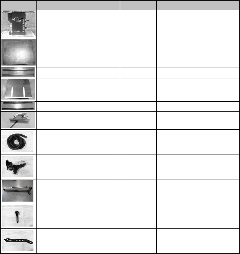
Loose Parts Inventory
The following depicts items shipped with your machine. Before assembling your saw, ensure that you have received all
parts shown below. Machine parts should arrive sealed in plastic bags. Remove parts from plastic bags before laying them
out to inventory them.
REF
Description
Q
PACKAGING
F3
Table
1
Wooden Crate
Right Extension Table
1
Boxed Individually
Right Extension Legs
2
Boxed with Outboard Table
Rear
Extension
Table
1
Boxed Individually
Rear Extension Table Legs
2
Each
leg
Boxed
individually
Miter Gauge
1
Boxed Individually
Dust Collection Hose
1
Plastic Wrapped Individually
Blade
Guard Assembly
1
Boxed Individually
Fence
Assembly
1
Boxed Individually
Fence Lock Knob
1
Boxed w/ Fence Assembly
Push Stick
1
Boxed w/ Fence Assembly
Fusion 3 Table Saw \ Setup \ Inventory List
18
© 2020 Laguna Tools
REF
Description
Q
PACKAGING
Left Side Front Rail
1
Boxed w/ Fence Assembly
Front Rail Assembly
1
Boxed Individually
Rear Rail Assembly
1
Boxed with Steel Rail
Control
Switch
1
Attached to table
Dust Collector Hose
1
Boxed Individually
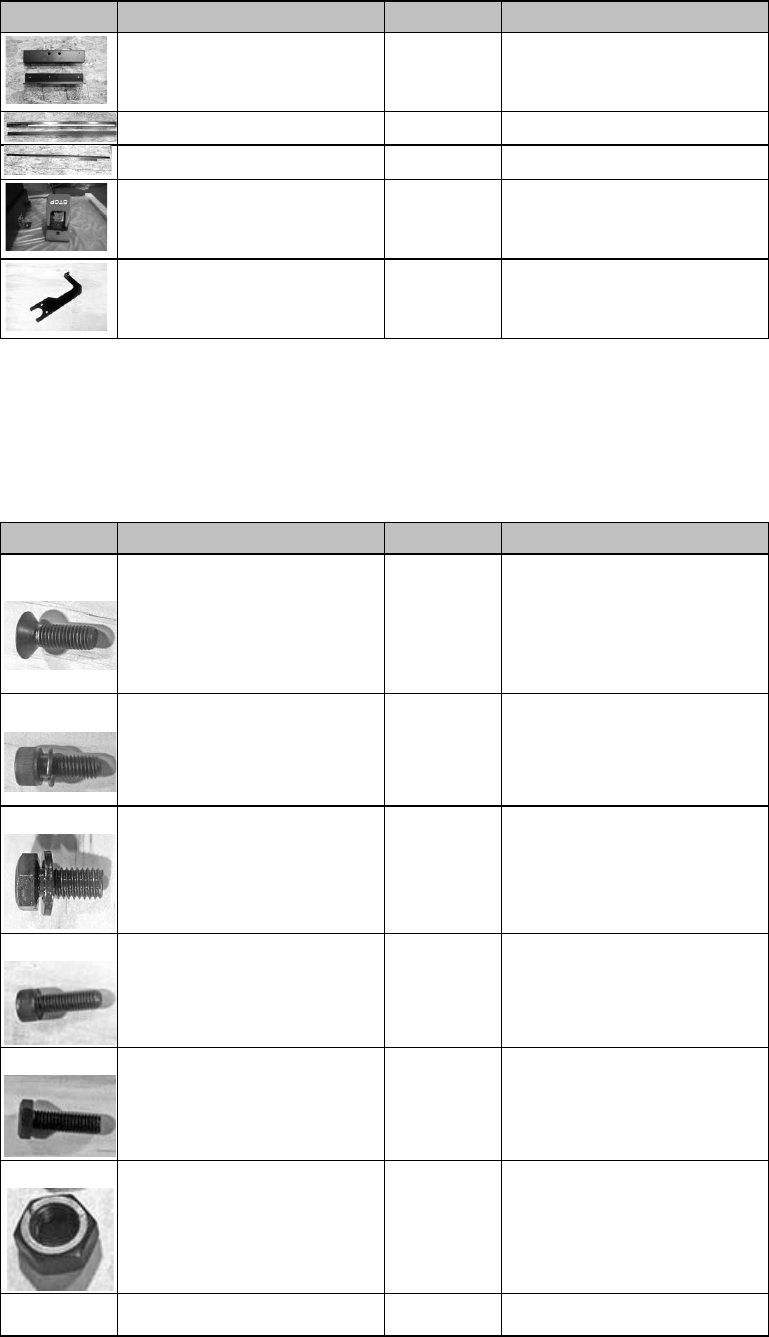
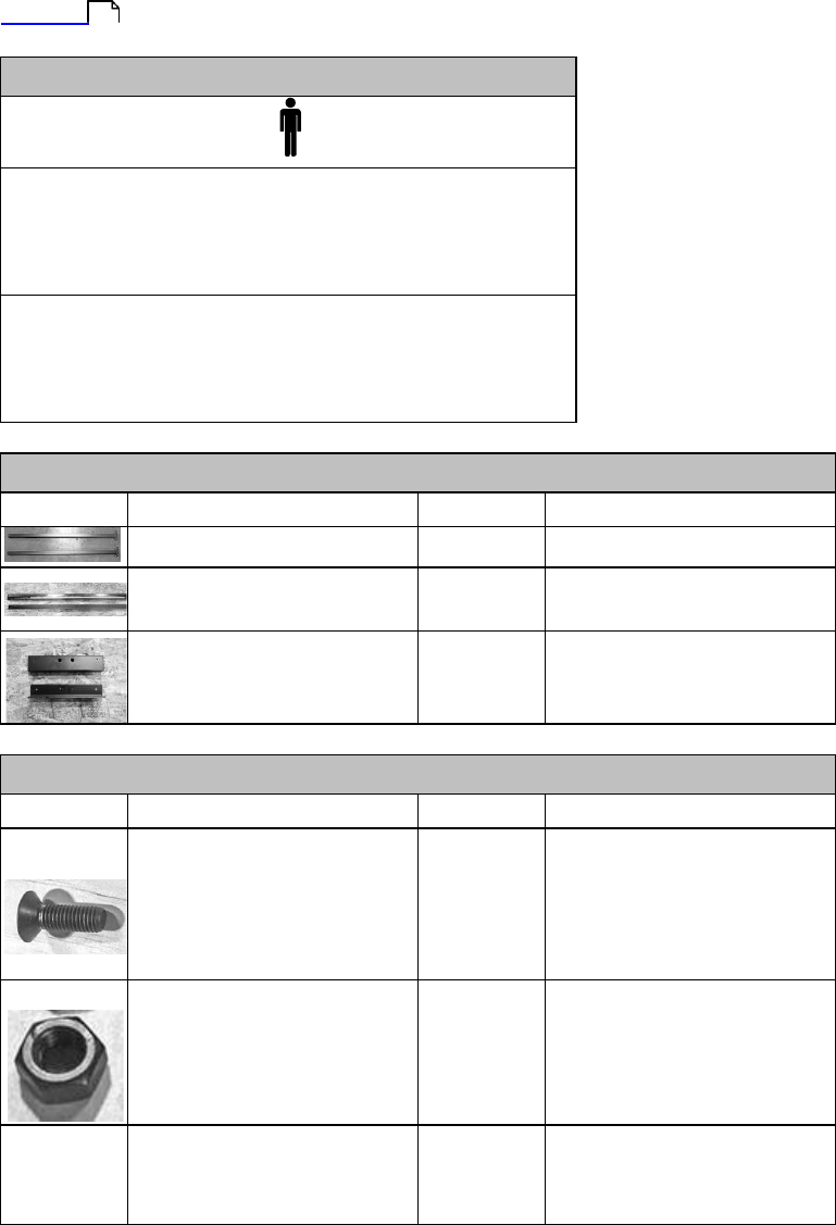
Hardware
Inventory
Listed below are all the hardware required for assembly of the Fusion F3 table saws. The hardware below has been
included in the Fusion F3’s packaging. As you inventory the other parts shipped with your machine, be sure to inventory and
familiarize yourself with the hardware listed below.
Ref.
Description
Q
Installation
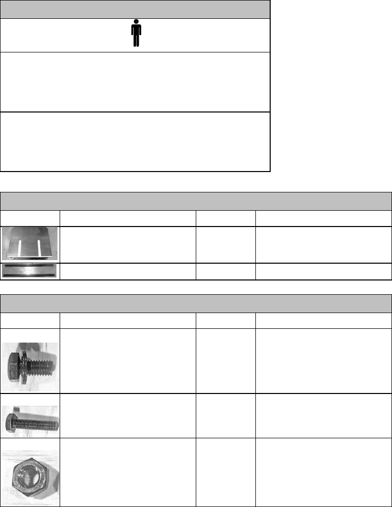
A
Counter-Sunk Alan Head
Screws (25mm)
use with hex nuts(F), flat
washers(H)
7
Front Rail Assembly, F3 Table
Also used to fasten Right
Extension Table
B
Socket head Button Screw w/
Lock Washer (28mm)
use with hex nuts(F), flat
washers(H)
4
Rear Rail Assembly, F3 Table
Dust collector hose support,
F3 Table
C
Hex Cap Screw w/ Flat Washer
(longer)
5
Rear Extension Table, F3 Table
Control Switch, Left Front Rail
D
Socket Head Cap Screw (no
washer) (28mm)
use with use with hex nuts(F),
lock washers (E)
5
Rear Rail
Assembly,
F3 Table
E
Hex Cap Bolt (30mm)
use with hex nuts(F), lock
washers (E)
2
Left Side Front Rail Assembly,
F3 Table
F
Hex Nuts (13mm)
20
Multiple
G
Flat Washers (8mm)
17
Multiple

Fusion 3 Table Saw \ Setup \ Inventory List
© 2020 Laguna Tools
19
Ref.
Description
Q
Installation
H
Lock Washers (8mm)
8
Multiple
I
Hex Cap Bolt (51mm)
use with Nylon Lock Nuts(H)
4
Rear Extension Table Legs,
Rear Extension table
J
Nylon Lock Nuts (16mm)
4
Rear Extension Table Legs,
Rear Extension table
K
Rubber
Feet
2
F3 Table (Bottom)
L
Hex Cap Screw w/ Flat Washer
(shorter)
9
Front Body to Front Rail (left &
right side)
Fusion 3 Table Saw \ Setup \ Inventory List
20
© 2020 Laguna Tools
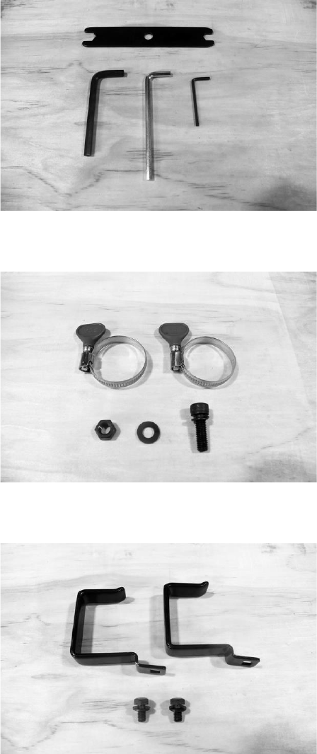
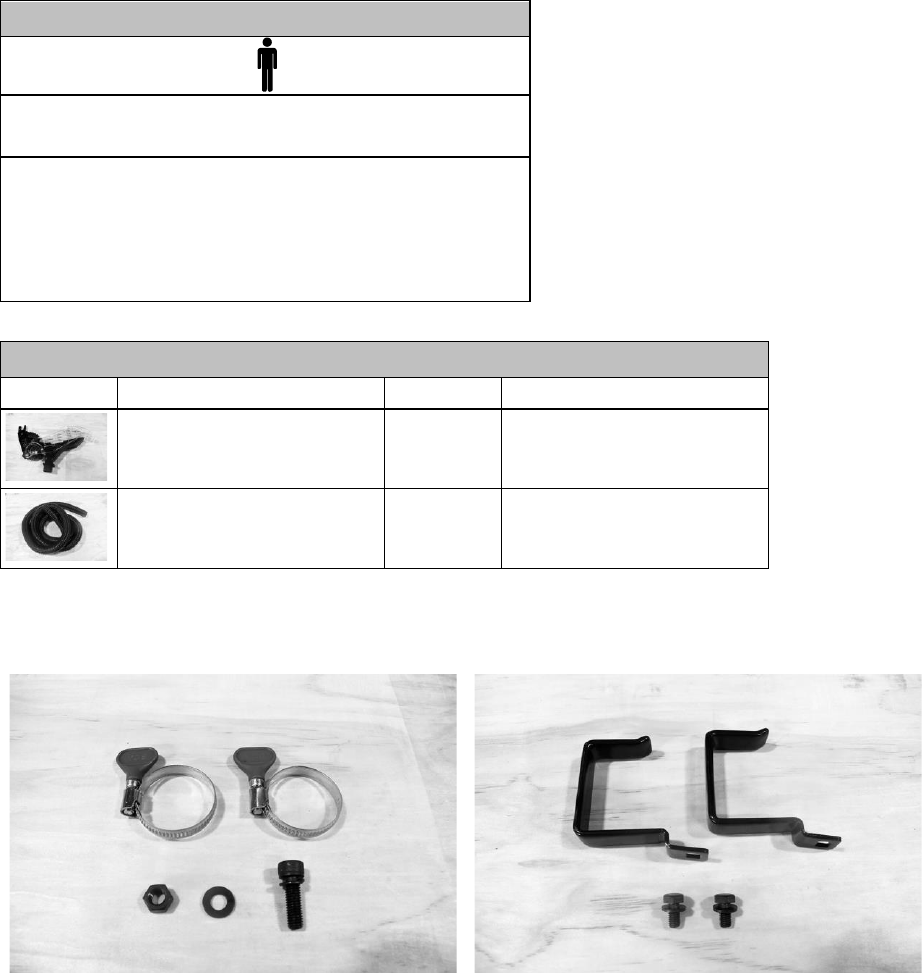
Accessory Hardware & Tools
NOTICE! The hardware and tools listed below come individually wrapped in plastic bags.
General Tools: dual-sided wrench and Allen
wrenches.
Band clamp with hex bolt, flat washer, and hex nut.
Fence hooks and hex bolts with flat washers.
Fusion 3 Table Saw \ Setup \ Unboxing
© 2020 Laguna Tools
21
Unboxing
Your Fusion F3 table saw was carefully packaged for safe transport. The table saw should arrive attached to a wooden
pallet and covered by a wooden crate housing the table saw and its accessories. When unpacking your machine, separate
all enclosed materials to ensure that there are no damages to the parts you’ve received. See pages 6-7 to cross reference
the parts you should receive with your table saw.
Do not plug in the machine until setup is complete.
Allays unplug the machine prior to any maintenance or setup work.
This machine is heavy. If you have any doubt about the following unboxing or set up procedures
seek assistance from an experienced professional. DO NOT attempt any procedure that you feel
is unsafe or that you feel you do not have the physical capability of achieving.
Do not cut deep into the wooden crate with a blade as it may scratch the paint of the table saw.
To prevent this, only use a dull edge or cut deep enough to only puncture the tape.
Before setting up your machine, organize all additional set-up tools. The package will arrive fitted
to a wooden pallet.
Quick
Reference
Guide
Add.
Required Tools:
Phillips head Screwdriver
Standard wrench
Shop Rag
WD40 (Cleaning solvent)
Troubleshooting/Tips:
Use at least two people to lift the wooden crate covering the
table saw and its accessories.
Unboxing
1)
Using a Phillips head screwdriver, remove the screws lining the bottom of the wooden crate. This will release the crate
covering from the wooden pallet.

Fusion 3 Table Saw \ Setup \ Unboxing
22
© 2020 Laguna Tools
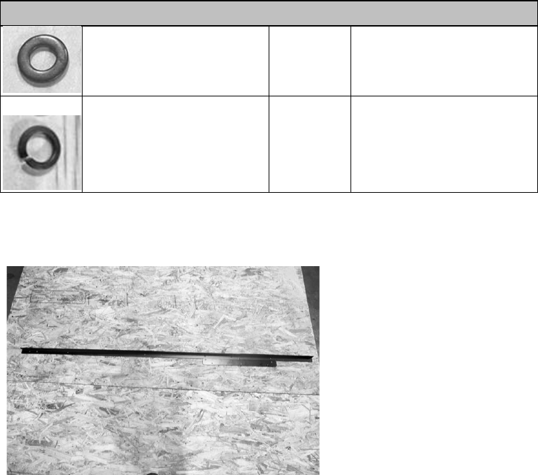
Shipped
Cartons w/52” Fence Rails
(Only 1 crate with 36” Fence Rails, inside)
Bolt
Locations
Screwing out skid bolts
You will need TWO OR MORE people to assist in completing step two.
2) With another person, lift the wooden crate off the wooden pallet. The table saw and individually boxed accessories will
be located beneath.
3)
Remove individually packaged items and inventory parts to ensure all parts have arrived undamaged.
Un-crated carton
Removing
the
table
saw
from
the
wooden
pallet:
Fusion 3 Table Saw \ Setup \ Unboxing
© 2020 Laguna Tools
23
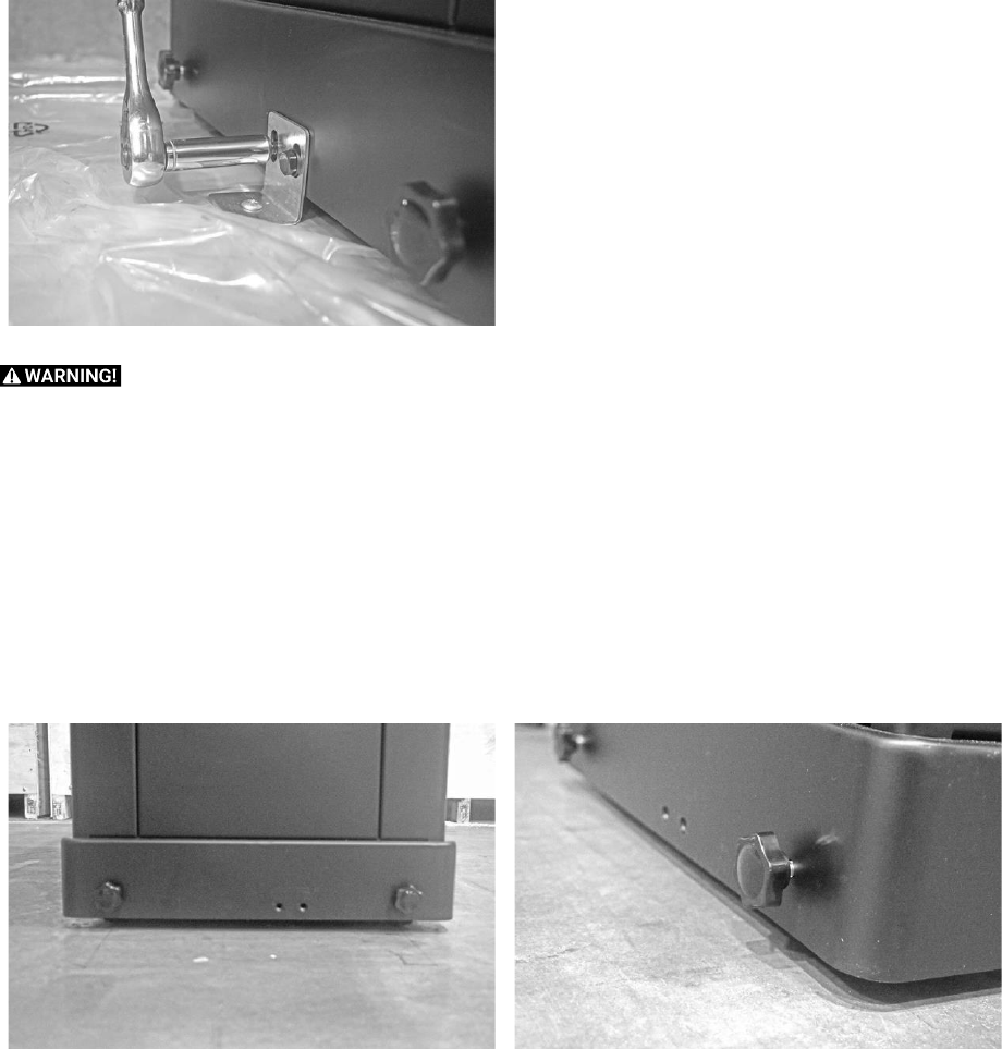
NOTICE! The table saw will arrive secured to the wooden pallet.
1) Using the 13mm socket wrench provided or a standard wrench, loosen the bolts attaching the table saw to the pallet’s
metal L brackets.
Bolt
Removal
It is recommended that TWO OR MORE people assist in completing step two. However, one person can
complete the remaining unboxing steps without further assistance.
2)
Preferably with another person, slowly walk the table saw off the wooden pallet.
3)
For safe assembly, place the table saw in a well-lit, location free of any debris or obstructions.
Table Saw Mobility:
1. At the base of the table saw, there are two lock knobs (shown right) which allow the user to adjust the wheels located
beneath the table saw. Tightening the knobs will lock the table saw’s wheels. Loosen the knobs to allow wheels to
move. After the knobs have been adjusted, lift the table saw from the opposite end (like a wheelbarrow).
Knob
Location
Loosening Lock Knobs
Fusion 3 Table Saw \ Setup \ Front Rail
24
© 2020 Laguna Tools
16
Front
Rail
The Fusion F3 table saw’s front rail assembly houses the front rail and guide ruler. In conjunction with the rear rail, the front
rail allows the fence to move fluidly across the table. The front rail assembly is made up of the left and right front rail
brackets, the front rail, and the control switch.
NOTICE! Make sure to level the saw to the foundation prior to leveling anything to the saw body. Please read the
Overview
prior to doing anything.
Quick
Reference
Guide
Add.
Required Tools:
Level
Allen Wrenches
General Wrench
Troubleshooting/Tips:
Attaching the rubber feet to the rear extension legs before
attaching the legs to the front rail bracket will make for easier
assembly.
Parts
REF
Description
Q
Installation
Right Extension Legs
2
Front Rail Assembly
Front Rail Assembly (Only the
front rail bracket is needed)
1
F3
Table
Left Side Front Rail
1
F3 Table
Rail
Body
Hardware
REF
Description
Q
Installation
A
Counter-Sunk Alan Head
Screws (25mm)
use with hex nuts(F), flat
washers(H)
5 of 7
Front Rail Assembly, F3 Table
Also used to fasten Right
Extension Table
F
Hex Nuts (13mm)
5 of 20
Front Rail Assembly, F3 Table
G
Flat Washers (8mm)
5 of 17
Front Rail Assembly, F3 Table
Fusion 3 Table Saw \ Setup \ Front Rail
© 2020 Laguna Tools
25
Hardware
E
Hex Cap Bolt (30mm)
use with hex nuts(F), lock
washers (E)
2 of 2
Left Side Front Rail Assembly,
F3 Table
H
Lock Washers (8mm)
2 of 8
Left Side Front Rail Assembly,
F3 Table
K
Rubber
Feet
2 of 2
Right Extension Leg
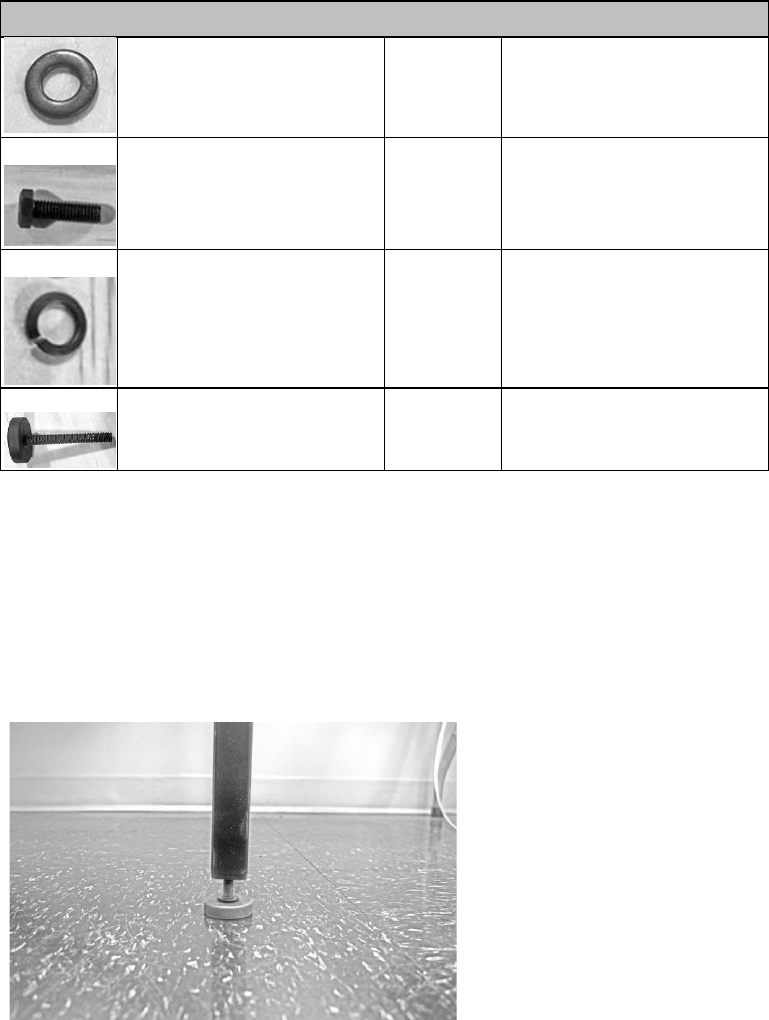
Attaching
the
Rubber
Feet
to
the
Right
Extension
Legs:
1.
Locate the threaded holes on the bottom of each of the right extension legs.
2.
Thread each rubber foot through the right extension leg’s bottom threaded holes.
3.
Hand-tighten each foot to start. Later, the foot may need to be loosened or tightened in order to properly level the front
and rear rails.
Correctly installed foot:
NOTICE!
You may assemble both right extension legs at this step, though only one will be used to complete the following
steps.
Attaching
the
Extension
Legs
to
the
Front
Rail
Bracket:
1.
Align the right extension leg’s bolt holes with the matching set of holes on the front rail bracket (located on the far right
of the bracket).
2.
Thread the counter-sunk bolts from the front rail through to the extension leg.
3.
Thread a lock washer and hex nut to on the back of the counter-sunk bolt.
4.
Secure the counter-sunk bolt to the front rail using an Allen wrench.
Fusion 3 Table Saw \ Setup \ Front Rail
26
© 2020 Laguna Tools
Front
View
Rear
View
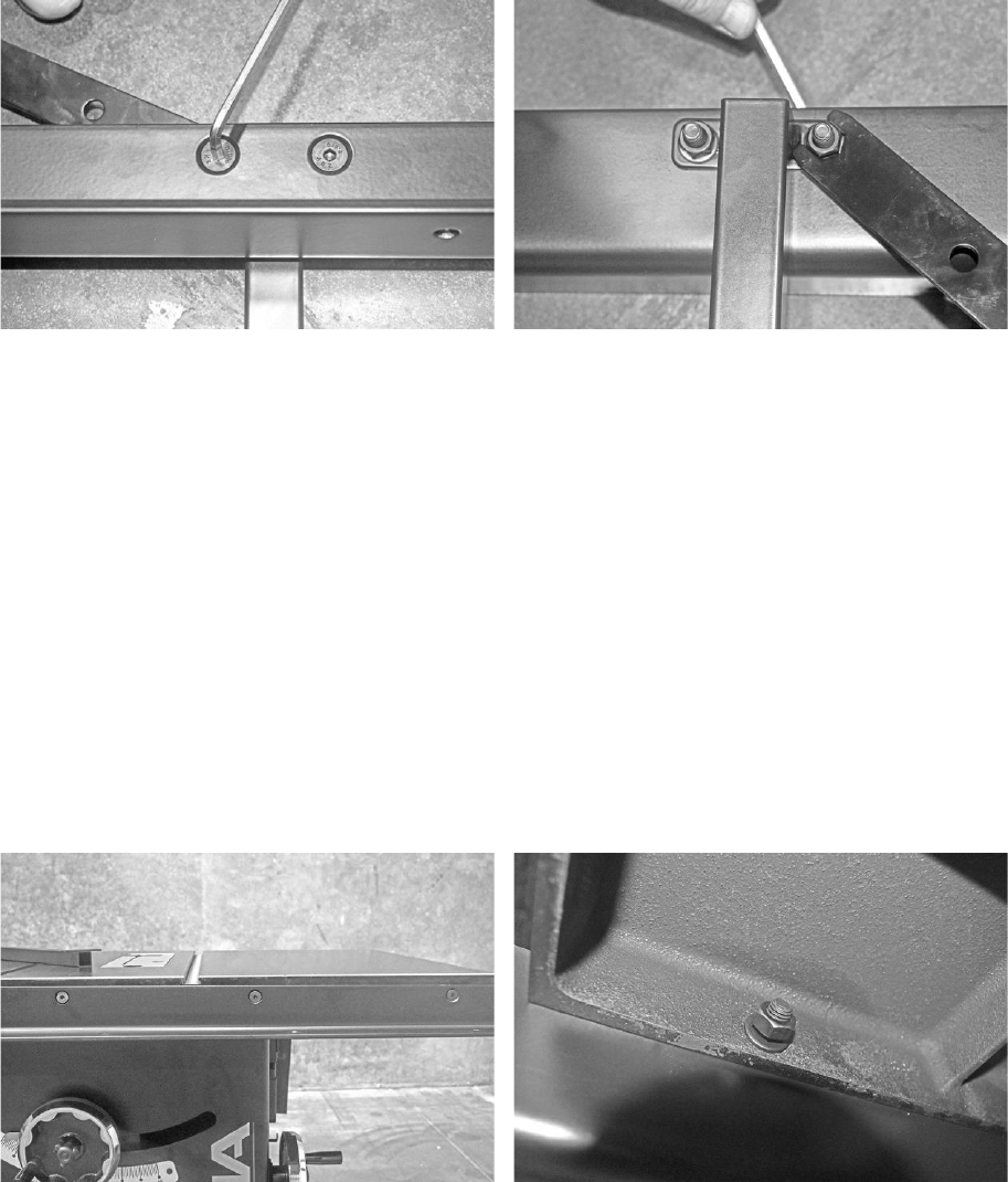
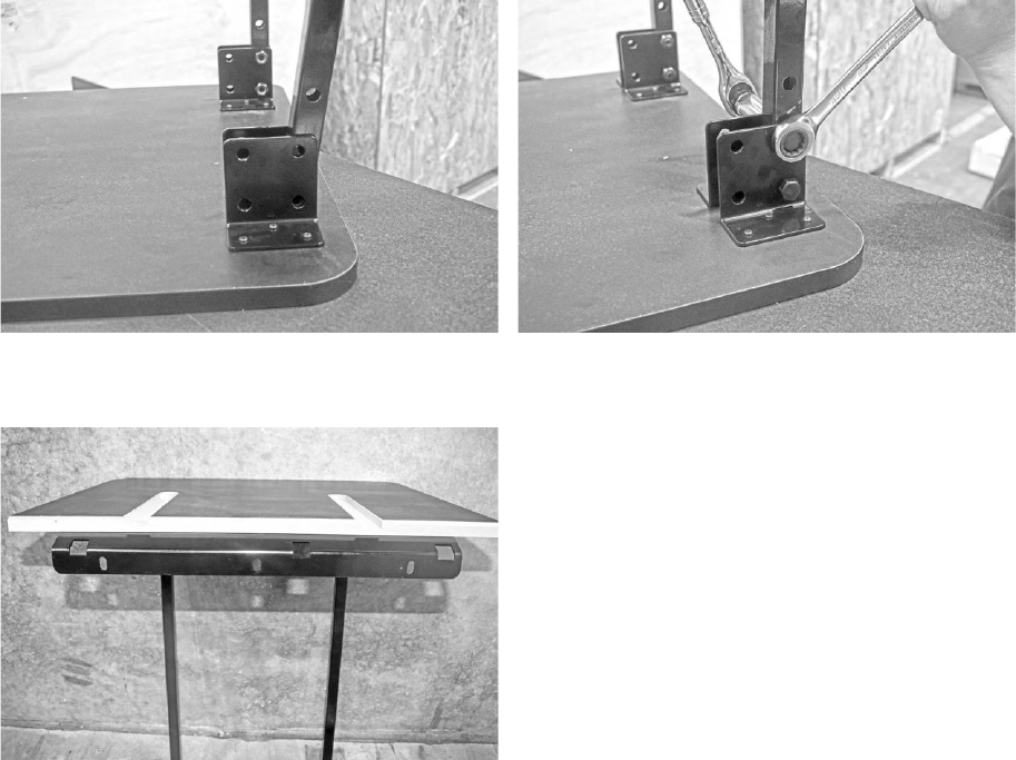
Attaching
the Right Front Rail
to
the Table:
1.
Align the
front bracket’s through holes with the through holes on the
front of the
table.
NOTICE!
The front rail bracket has three through-holes which should align with the last three through-holes on the front of
the table located on the far right as shown.
2.
Thread three counter-sunk screws through each of the front rail’s through-holes.
3.
Thread the flat washers and hex nuts onto the back of each counter-sunk bolt.
4.
Use a level to ensure that the front rail is level to the table. If needed, you may adjust the height of the extension leg to
level the bracket with the table.
5.
After the bracket has been leveled, tighten the counter-sunk bolts with the wrench provided to secure the bracket to the
table.
NOTICE!
After completing step four, there should be two through holes in the middle of the front rail bracket which have not
been used yet. These should be empty as they will be used to mount the right
extension table later.
Three Front Rail Counter-Sunk Bolts Flat Washer and Hex Nut (secured to the table)
Fusion 3 Table Saw \ Setup \ Front Rail
© 2020 Laguna Tools
27
Middle counter-sunk through holes (empty):
Attaching the Left Front Rail to
the Table:
1.
Align the left front rail’s bolt holes with the bolt holes on the front of the table saw.
NOTICE!
These bolt holes will be located to the far left on the front of the table.
2.
Place a lock washer onto the head side of the 30 mm hex bolts. Then thread two 30 mm hex bolts through each of the
left front rail’s bolt holes.
3.
Thread a flat washer and hex nut onto the back of the 30 mm hex bolt.
4.
Hand-tighten the bolts to secure the left front rail to the table. Then, use a level to ensure that the left front rail bracket is
leveled.
5.
After the left front rail bracket has been leveled, tighten the hex bolts using the wrench provided.
Left front rail and level
Flat Washer and Hex Nut (secured to the table)
Fusion 3 Table Saw \ Setup \ Rear Rail
28
© 2020 Laguna Tools
Rear
Rail
The Fusion F3 table saw’s rear rail assembly supports both the fence and the rear extension table attachment. In
conjunction with the front rail, the rear rail allows the fence to move fluidly across the table. The rear rail assembly is made
up of the left and right rear rail bracket, the dust collector hose support bracket, the rear rail bracket.
Quick
Reference
Guide
Add.
Required Tools:
Level
Allen Wrenches
General Wrench
Troubleshooting/Tips:
Attaching the dust collector hose support to the right rear rail
bracket BEFORE attaching the right extension leg to the
bracket will make for easier assembly.
Parts
REF
Description
Q
Installation
Right Extension Legs
(now
assembled)
2
Assembled to F3 Table
Rear Rail Assembly
1
F3
Table
Dust Collector Hose
1
Right Rear Rail Bracket
Hardware
REF
Description
Q
Installation
B
Socket head Button Screw w/
Lock Washer (28mm)
use with hex nuts(F), flat
washers(H)
4 of 4
Rear Rail Assembly, F3 Table
Dust collector hose support,
F3 Table
D
Socket Head Cap Screw (no
washer) (28mm)
use with hex nuts(F), flat
washers(H), lock washers(H)
3 of 5
Rear Rail
Assembly,
F3 Table
F
Hex Nuts (13mm)
7 of 20
Rear Rail
Assembly,
F3 Table
G
Flat Washers (8mm)
7 of 17
Rear Rail
Assembly,
F3 Table
Fusion 3 Table Saw \ Setup \ Rear Rail
© 2020 Laguna Tools
29
Hardware
H
Lock Washers (8mm)
3 of 8
Rear Rail
Assembly,
F3 Table
From left to right: Right Rear Rail Bracket, Left Rear
Rail Bracket, Rear Rail Bracket (centered).
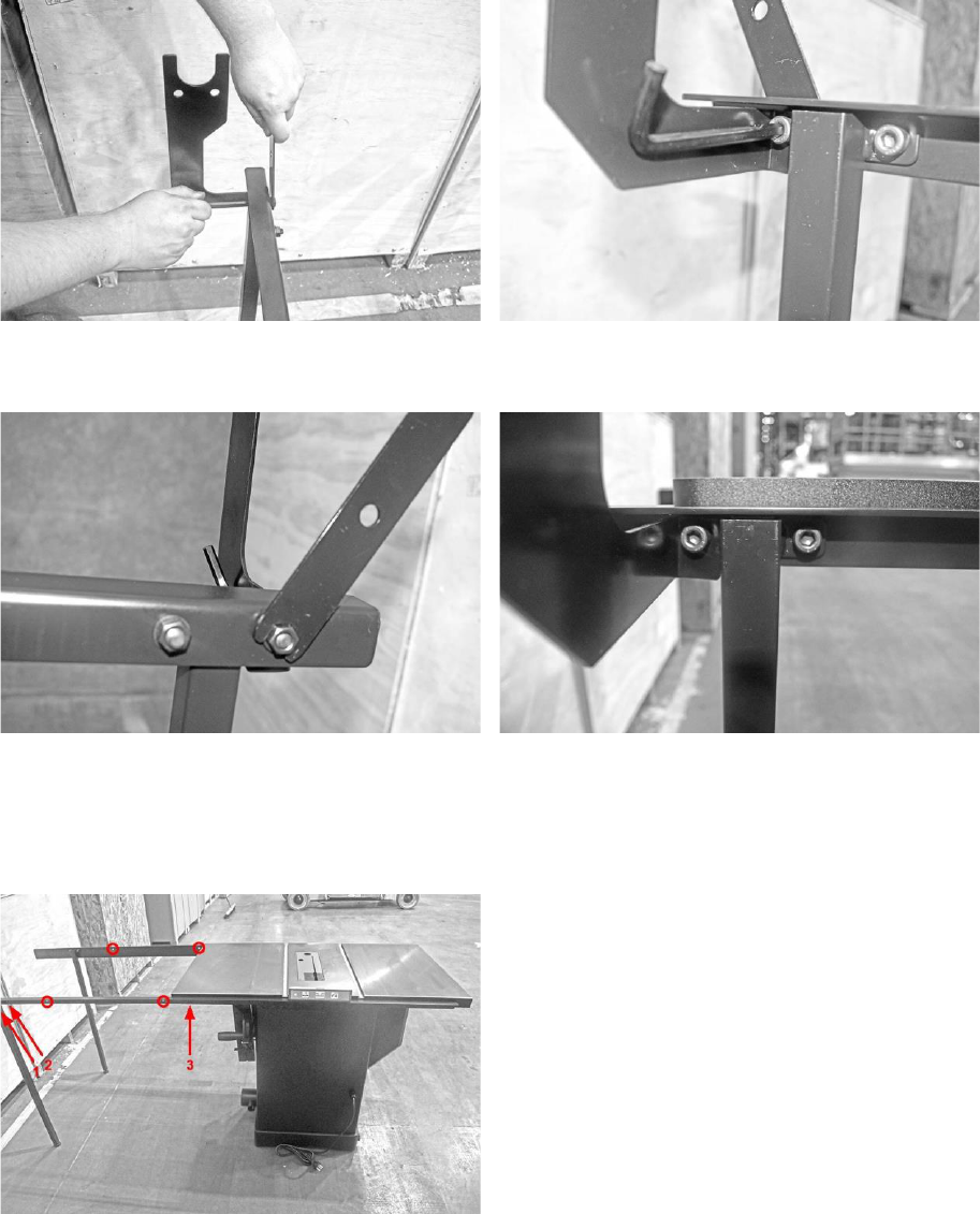
Attaching the Rear Extension Leg and Dust Collector Hose Support Bracket to the
Right Rear Rail Bracket:
NOTICE! You will need to attach the dust collector hose support bracket to the right rear rail bracket, as they share an
assembly bolt.
1.
Align the right extension leg with the matching set of bolt holes at the end of the right rear rail bracket.
2.
Using one socket head cap screw, secure the right extension leg to the rear right rail bracket. This will ensure that the
leg does not move as the dust collector hose support is being attached to the rail and extension leg.
3.
Align the dust collector hose support’s bolt hole with the bolt hole farthest right on the right rear rail bracket. The dust
collector hose should then also be aligned with the extension leg’s furthest right bolt hole.
4.
Secure the dust collector hose support, right rear rail bracket, and right extension leg to the table.
NOTICE! Thread lock washers to the head of the screws. Secure flat washers and hex nuts to the back of the screw.
Fusion 3 Table Saw \ Setup \ Rear Rail
30
© 2020 Laguna Tools
Top View: Front View:
Rear
View: Hose support and Leg properly Installed:
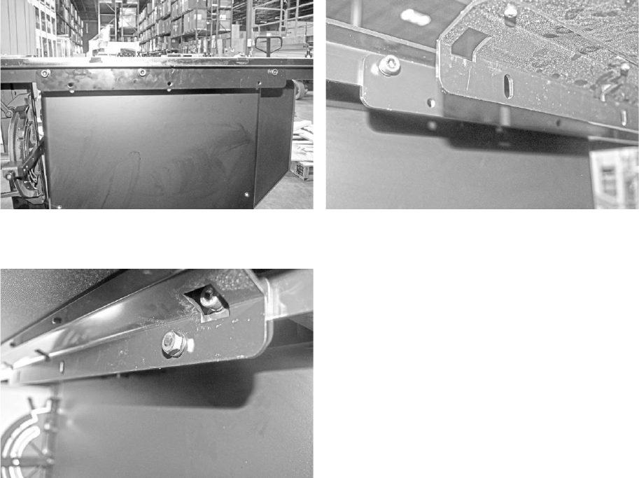
Attaching
the
Right
Rear
Rail
Bracket
to
the
Table:
1.
Align the right rear rail bracket’s bolt holes with the bolt holes located on the back of the table as shown below:
2.
Thread 1 socket head cap screws and lock washer through the rear rail and table’s through holes. At this stage, only
three socket head cap screws should be used to secure the rail to the table (see above image).
3.
Thread flat washer and hex nut and snugly tighten, allowing play.
Fusion 3 Table Saw \ Setup \ Rear Rail
© 2020 Laguna Tools
31
NOTICE!
After completing step two, there should be two through holes in the middle of the front rail bracket which have not
been used yet. These should be empty as they will be used later to mount the right extension table (shown above as red
circles)
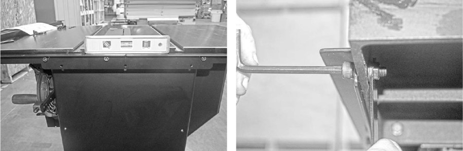
Attaching
the Left Rear
Rail
Bracket and
Rear
Bracket to
the Table:
1.
Align the left rear rail bracket’s threaded bolt holes with the bolt holes located on the far left of the table saw.
2.
Place the rear rail bracket over the right and left rear rail brackets. (pictured below).
3.
Align the rear rail’s bolt holes with the left and right rear rail’s bolt holes as shown.
4.
Thread socket head cap screws and lock washers through the rear rail assembly.
5.
Thread flat washers and hex bolts on to the back of the socket head cap screws, make sure the rails are level to the
table, and tighten to secure all brackets to the table.
NOTICE! Ensure that the through holes (not the threaded holes) on the rear rail brackets are used for this step. The
threaded holes will be used later to attach the rear extension table to the table saw.
Leveling:
Bolt Tightening and arrangement: Bolt, lock washer
//
flat washer, nut
Fusion 3 Table Saw \ Setup \ Right Extension Table
32
© 2020 Laguna Tools
Right
Extension
Table
The Fusion F3 table saw’s right extension table supports both the fence and the work piece. In conjunction with the front
rail, the right extension table allows the fence to move fluidly across the table to adjust to the width of the wood piece being
cut.
Quick
Reference
Guide
Add.
Required Tools:
Level
Allen Wrenches
General Wrench
Troubleshooting/Tips:
Be sure that the right extension table’s grooves are fitted
snugly on the threads of the screws/bolts before securing the
extension table to the rear rails.
Parts
REF
Description
Q
Installation
Right Extension Table
1
Right Rear Rail, F3 Table, Right
Front Rail
Hardware
REF
Description
Q
Installation
A
Counter-Sunk Alan Head
Screws (25mm)
use with hex nuts(F), flat
washers(H)
2 of 7
Front Rail Assembly, F3 Table,
Right Extension Table
D
Socket Head Cap Screw (no
washer) (28mm)
use with hex nuts(F), flat
washers(H), lock washers(H)
2 of 5
Rear Rail Assembly, F3 Table,
Right Extension Table
F
Hex Nuts (13mm)
4 of 20
Multiple
G
Flat Washers (8mm)
4 of 17
Multiple
H
Lock Washers (8mm)
2 of 8
Socket Head Cap Screw

Fusion 3 Table Saw \ Setup \ Right Extension Table
© 2020 Laguna Tools
33
Hardware
Mounting the Table Extension:
1.
Thread two counter sunk bolts through the two available through holes on the front rail bracket.
2.
Thread two socket head cap screws through the available bolt holes on the right ear rail bracket.
3.
Place the right extension table’s grooves on top of the socket head and counter-sunk screws respectively. Ensure that
each of the four the grooves are securely rested on the threads of each of the exposed screws.
4.
Thread flat washers and hex nuts on the backs of each of the screws. Use the wrench to tighten the bolts and secure
the extension table to the front and rear rails.
Pre-Installation:
Underside Bracket (the picture does not show a flat
washer used, please use one)
Completed installation:
Fusion 3 Table Saw \ Setup \ Rear Extension Table
34
© 2020 Laguna Tools
Rear
Extension
Table
The Fusion F3 table saw’s rear extension table supports both the fence and the work piece. In conjunction with the rear rail,
the rear extension table provides an extra support table for the length of the wood piece being cut.
Quick
Reference
Guide
Add.
Required Tools:
Level
General Wrench
17mm socket wrench (optional)
Troubleshooting/Tips:
For easiest assembly, flip the rear extension table so that the
face is down. After the table has been flipped, attach the rear
extension legs to the table.
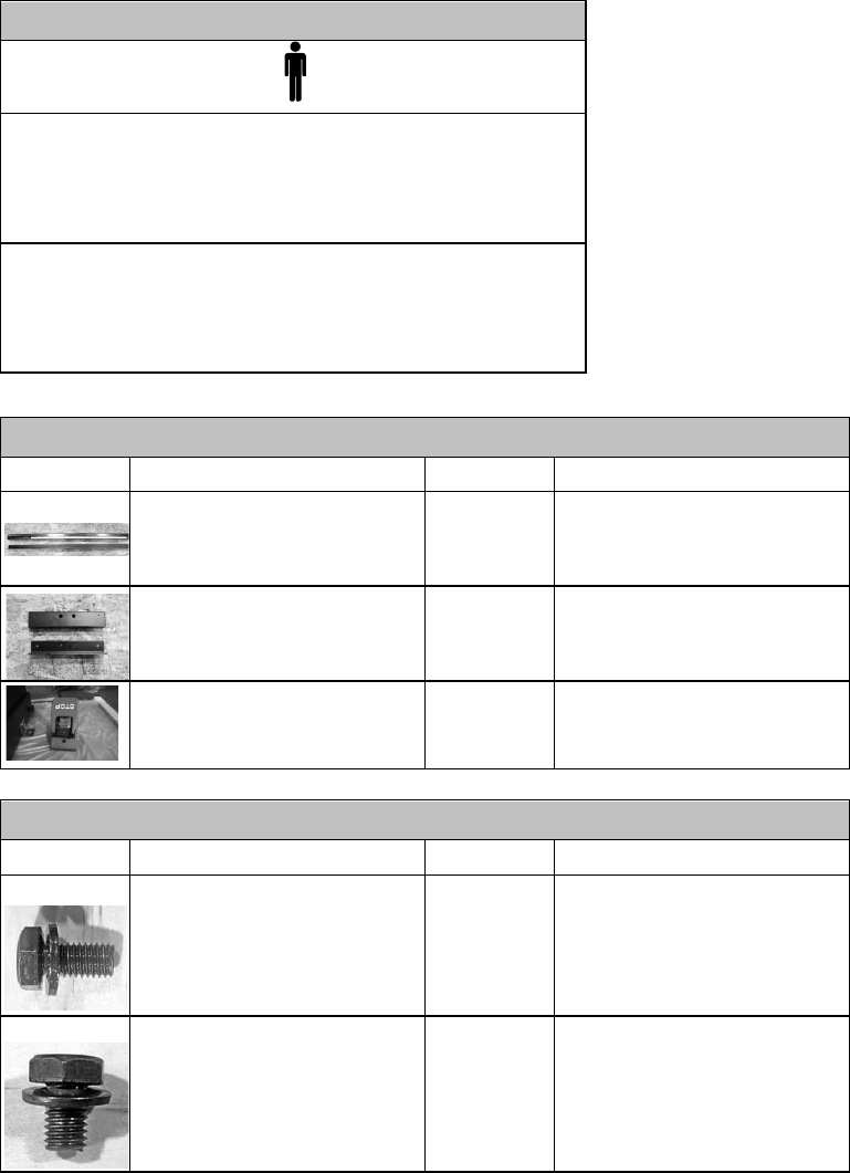
Parts
REF
Description
Q
Installation
Rear
Extension
Table
1
Rear Rail
Assembly,
F3 Table
Rear Extension Table Legs
2
Rear
Extension
Table
Hardware
REF
Description
Q
Installation
C
Hex Cap Screw w/ Flat Washer
(longer)
3 of 5
Rear Extension
Table,
F3 Table
I
Hex Cap Bolt (51mm)
use with Nylon Lock Nuts(H)
4 of 4
Rear Extension Table Legs,
Rear Extension table
J
Nylon Lock Nuts (16mm)
4 of 4
Rear Extension Table Legs,
Rear Extension table
Attaching Legs to the Rear Extension Table:
1.
Flip the rear extension table so that the face is down.
2.
Place the rear extension legs between the metal L-brackets on either side of the table.
3.
Align the rear extension leg’s bolt holes with bracket’s bolt holes. Ensure that the rear extension leg’s bolt holes are
aligned with the last two bolt holes of the metal bracket.
Fusion 3 Table Saw \ Setup \ Rear Extension Table
© 2020 Laguna Tools
35
4.
Thread the 51 mm hex bolts through the metal L-bracket.
5.
Thread nylon lock nuts on to the back of the hex bolts. Tighten with a wrench or a 17 mm socket wrench (optional).
Attaching legs to table:
Securing
Bolts
Installed
Legs
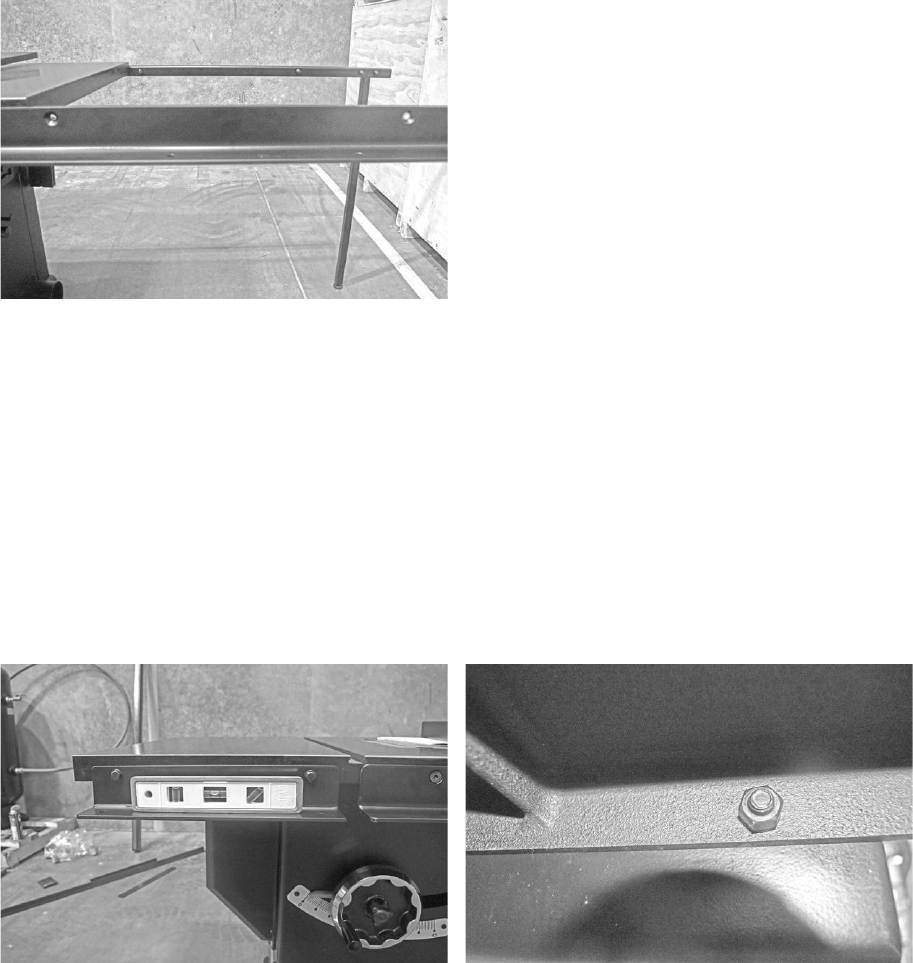
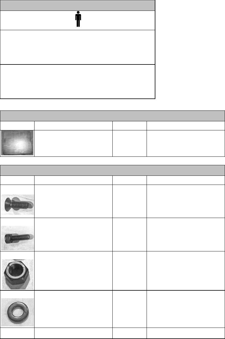
Attaching
the
Rear
Extension
Table
to
the
Table
Saw:
1.
Locate the three through holes on the back mounting bracket of the rear extension table.
2.
Align these three through holes with the three threaded holes on the rear support bracket.
3.
Thread one of the three (longer) Hex Bolt with Flat Washer through each of the threaded holes.
NOTICE! The height of the rear extension table’s legs can be adjusted as needed to level the table.
Fusion 3 Table Saw \ Setup \ Rear Extension Table
36
© 2020 Laguna Tools
Pre-
installation
Aligning the bracket
Bolt into thread holes:
Fusion 3 Table Saw \ Setup \ Front Rail Pt.
2 & Control Switch
© 2020 Laguna Tools
37
Front Rail Pt. 2
& Control Switch
The Fusion F3 table saw’s front rail houses the control switch and front rail/guide ruler. The control switch allows the user
to quickly turn the machine on/off before and after making cuts. The front rail assembly provides the user with a guide to
measure the distance between the fence and the blade.
Quick
Reference
Guide
Add.
Required Tools:
Level
General Wrench
13mm socket wrench (optional)
Troubleshooting/Tips:
Be sure to attach the control switch to the left front rail from
underneath the front left rail bracket. This will allow the left
front rail block to fit properly on the left front rail bracket.
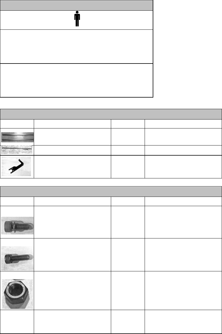
Parts
REF
Description
Q
Installation
Front Rail Assembly
(Rails previously assembly,
body is needed)
1
Body mounted to rail
Left Side Front Body (Rails
previously assembly, body is
needed)
1
F3 Table
Rail
Body
Control
Switch
1
Bolts onto Left side Rail
Hardware
REF
Description
Q
Installation
C
Hex Cap Screw w/ Flat Washer
(longer)
2 of 5
Control Switch, Left Front Rail
L
Hex Cap Screw w/ Flat Washer
(shorter)
9 of 9
Front Body to Front Rail (left &
right side)
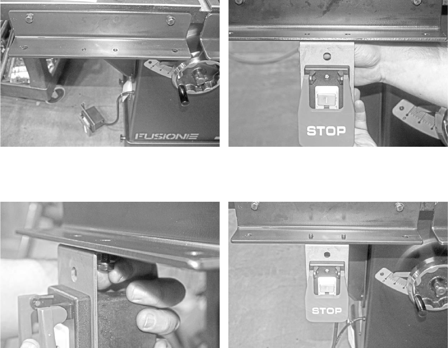
Mounting
the
Control
Switch
to
the
Left
Front
Rail:
1.
Align the bolt holes on the top of the control switch with the bolt holes on the bottom of the left front rail bracket.
Fusion 3 Table Saw \ Setup \ Front Rail Pt.
2 & Control Switch
38
© 2020 Laguna Tools
2.
Thread the 2 longer hex cap screw and flat washer through the control switch’s bolt holes.
3.
Tighten the bolts using either the general wrench or a 13 mm socket wrench to secure the control switch to the left front
rail bracket.
NOTICE! Ensure that the head of the hex bolts are threaded from underneath the left front rail. The ends of each the bolts
should be visible from the top of the left front rail.
Pre-
Installation:
Control Switch Placement:
Mounting Control Switch with 2 longer hex bolts and
flat washers
Control Switch correctly mounted. The expose bolts
will fit the through holes in the fence body
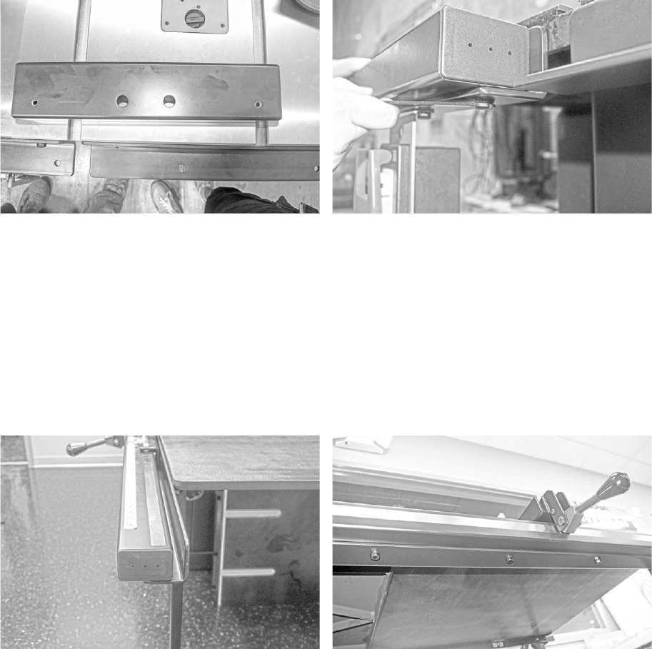
Mounting
the
Left Front Rail
Block
to
the Left Front Rail:
1.
Place the left front rail block on the left front rail bracket.
2.
Align the block’s outermost through holes with the bracket’s outermost through holes.
3.
Like mounting the control switch, thread the shorter hex bolts with flat washers from underneath the left front rail
bracket.
4.
Using either the general wrench or a socket wrench, tighten the bolts to secure the left front rail block to the left front rail
bracket.
Fusion 3 Table Saw \ Setup \ Front Rail Pt.
2 & Control Switch
© 2020 Laguna Tools
39
Pre-Installation
Attaching the left front rail body to the left front rail
using the shorter hex bolts and flat washers.
Mounting
the
Front
Rail
(with
Guide
Ruler):
1.
Place the front rail on the front rail bracket.
2.
Align the front rail’s bolt holes (located on the bottom of the front rail) with the front rail’s bolt holes.
3.
Thread shorter hex bolts with flat washer through each of the front rail’s bolt holes.
NOTICE!
Only hand-tighten the bolts
for now.
4.
Pull the rail out as far as it will allow first. This will allow space for the fence’s nylon slider to move through comfortably.
5.
Tighten each bolt using either the general wrench or a 13 mm socket wrench.
Front guide rail seated on front rail: Underside
View
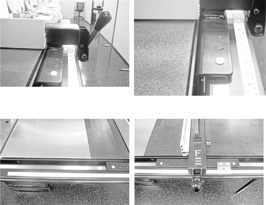
Fitting the Fence to the Table:
NOTICE! The table saw’s fence comes pre-assembled and will need no further assembly to put the unit together.
1.
Place the fence’s nylon sliders on the grooves between the front and back rails.
2.
Ensure that the fence’s locking gauge is placed over the edge of the front rail.
Fusion 3 Table Saw \ Setup \ Front Rail Pt.
2 & Control Switch
40
© 2020 Laguna Tools
Fence fitted over the front guide rail Detailed
view
Front of rail showing counter sunk screws Properly Installed Fence:
Fusion 3 Table Saw \ Setup \ Accessory Installation
© 2020 Laguna Tools
41
Accessory Installation
The Fusion F3 table saw’s supports several accessories which help the machine to run smoothly and function properly. The
accessories which come with your table saw are: a dust collector hose, a set of fence hooks, and a tool caddy (located
underneath the table).
Quick
Reference
Guide
Add.
Required Tools:
None
Troubleshooting/Tips:
The writhing knife can be found already attached to the blade
upon arrival. Be sure the machine is off, when you attempt to
remove the writing knife from its position on the back of the
blade.
Parts
REF
Description
Q
Installation
Blade
Guard Assembly
1
Boxed Individually
Dust Collection Hose
1
Blade-guard to Inlet
You will also need all the contents in the packages of:
Band clamp with hex bolt, flat washer, and hex nut. Fence hooks and hex bolts with flat washers.
Attaching
the
Dust
Collector
Hose:
1.
Attach a band clamp on the
mouth of the dust collector hose.
2.
Attach the hose to the dust port on the blade guard.
3.
Tighten the band clamp to secure the hose to the blade guard.
4.
Repeat steps one through three to attach the hose to the table saw’s 4” dust outlet.

Fusion 3 Table Saw \ Setup \ Accessory Installation
42
© 2020 Laguna Tools
Attaching hose to blade guard assembly: Attaching hose to dust port:
Attaching
the
Fence
Hooks
to
the
Table:
1.
Locate the fence hook bolt holes on the back of the table saw (located underneath the rear extension table).
2.
Thread the fence hook’s hex bolts through the fence hook’s bolt holes.
3.
Thread the hex bolts through the bolt holes on the back of the table saw.
4.
Tighten the hex bolts with the general wrench.
Fence Hook Installation Fence Hook Installation
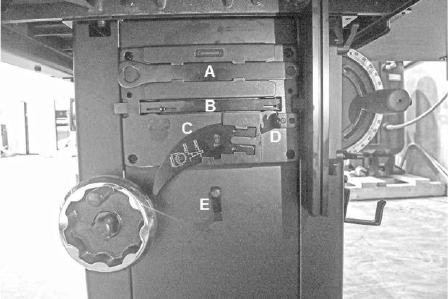
Tool Caddy:
The table saw’s tool caddy is located under the right extension table. The tool caddy provides a space to store the miter
gauge, the writing knife, and the blade wrench, and the general wrench when not in use.
See the picture shown below to see proper placement of these tools.
Fusion 3 Table Saw \ Setup \ Accessory Installation
© 2020 Laguna Tools
43
From Top Down: A. Arbor Wrench, B. Miter Gauge, C.
Riving Knife, D. Blade Guard Hook, E. Dust Hose
Wrapping Hook.
Your
F3 Table
Saw
is now
properly assembled.

Fusion 3 Table Saw \ Maintenance \
44
© 2020 Laguna Tools
.
Adjustments
Calibrating and adjusting the Tilt mechanism
MAINTENANCE & ADJUSTMENTS
ADJUSTING THE 45° & 90° BEVEL STOPS
1. Disconnect the machine from the power source.
2. Raise the blade to its highest position and lift the blade guard.
3. Loosen the bevel lock knob and turn the blade tilting handwheel clockwise until it stops.
4. Verify the angle of the blade with a combination square from the left side of the blade, keep the
square flat against the table and against the flat part of the blade. Do not touch the teeth or the table
insert.
If the blade 90° angle is incorrect, remove the motor cover G Fig. A by Philips screwdriver then loosen
the Hex. Nut C, Fig. B then turn the 90° stop screw D, Fig. B under the table by Hex. wrench. Turn the
hand wheel until the blade is at 90° to the table surface. Then re-tighten the 90° stop screw & Hex. nut
until slight resistance is felt. Do not over tighten stop screw.
Verify the 45° setting by tilting the blade as far as possible to the left and using the square, check the
angle and if needed adjust as for the 90° stop, this time remove the storage box H, Fig. C by Philips
screwdriver then loosen the Hex. Nut E, Fig. C then turn the 45° stop screw F, Fig. C under the table
by Hex. wrench. Turn the hand wheel until the blade is at 45° to the table surface. Then re-tighten the
45° stop screw & Hex. nut until slight resistance is felt. Do not over tighten stop screw.
WARNING: MAKE SURE THE SAW HAS BEEN TURNED OFF AND UNPLUGGED FROM THE POWER SOURCE
BEFORE PERFORMING ANY MAINTENANCE.
Fig. A
G
H
!
!
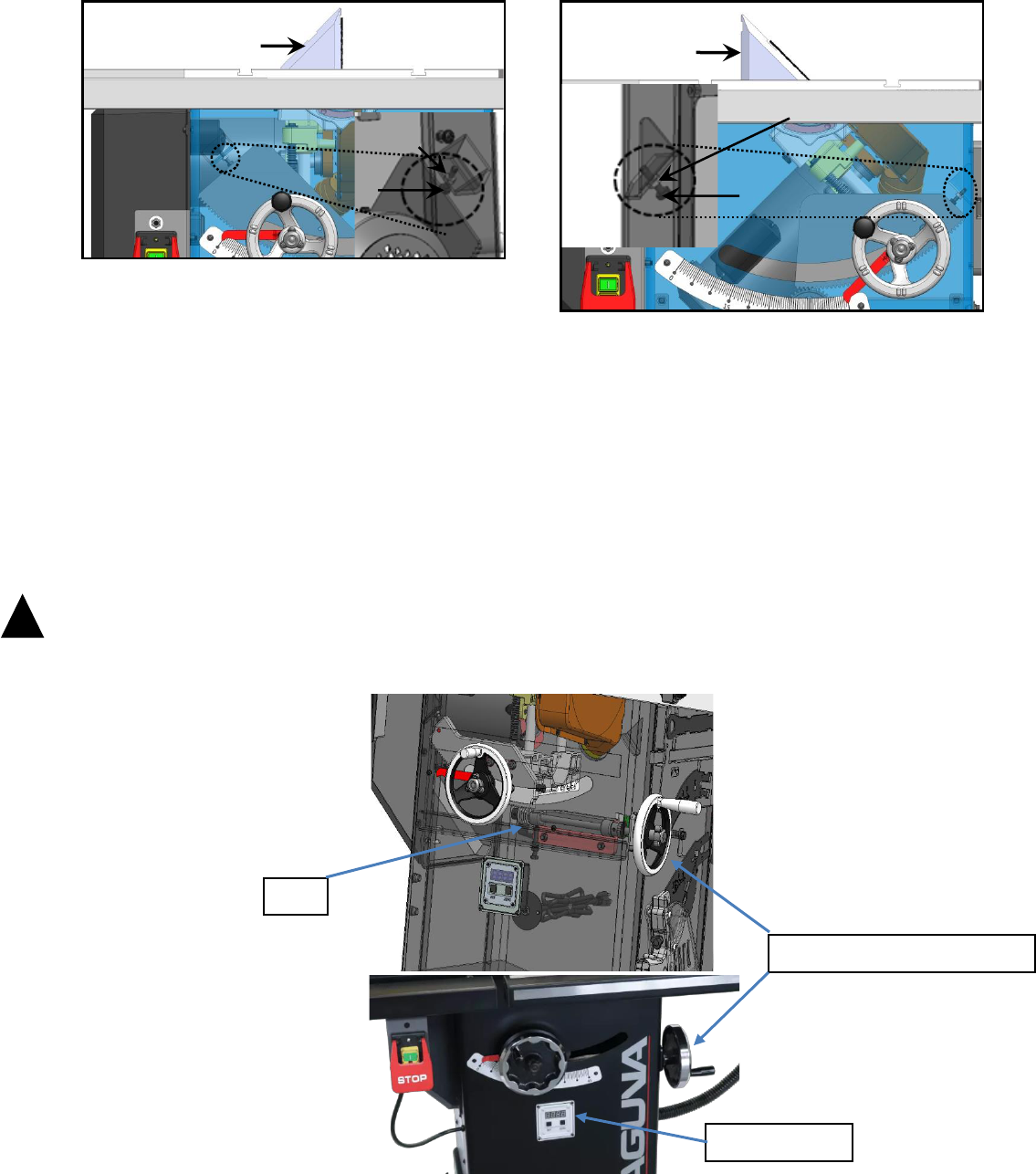
Fusion 3 Table Saw \ Troubleshooting \
© 2020 Laguna Tools
45
.
Fig. B
Fig. C
BLADE TILT /BEVEL ADJUSTMENT
The blade tilt (bevel) adjustment control by worm gear box assembly C, handwheel D is located on the side
of the saw, Figs. D & E.
Turn the handwheel C left or right as required to set the blade to the desired angle. The blade can be tilted
to the left anywhere from 0° (90° to the table) to 45°.
WARNING: TO LIMIT YOUR EXPOSURE TO THE BLADE AND ALSO TO MAXIMISE THE EFFECTIVENESS OF THE ANTI-KICKBACK
PAWLS (WHEN USING THE RIVING STYLE SPLITTER & BLADE GUARD), NEVER TAKE MORE BLADE HEIGHT THAN IS REQUIRED TO
COMPLETE THE CUT. WHEN SETTING THE BLADE HEIGHT FOR THROUGH-CUTS (CUTS ALL THE WAY THROUGH THE THICKNESS
OF A BOARD) SET THE HEIGHT OF THE BLADE TO ROUGHLY 1/4" HIGHER THAN THE THICKNESS OF THE BOARD.
Figs. D & E
!
!
DRO (angle)
D (Handwheel, angle)
C
A
C
D
C
A
F
E
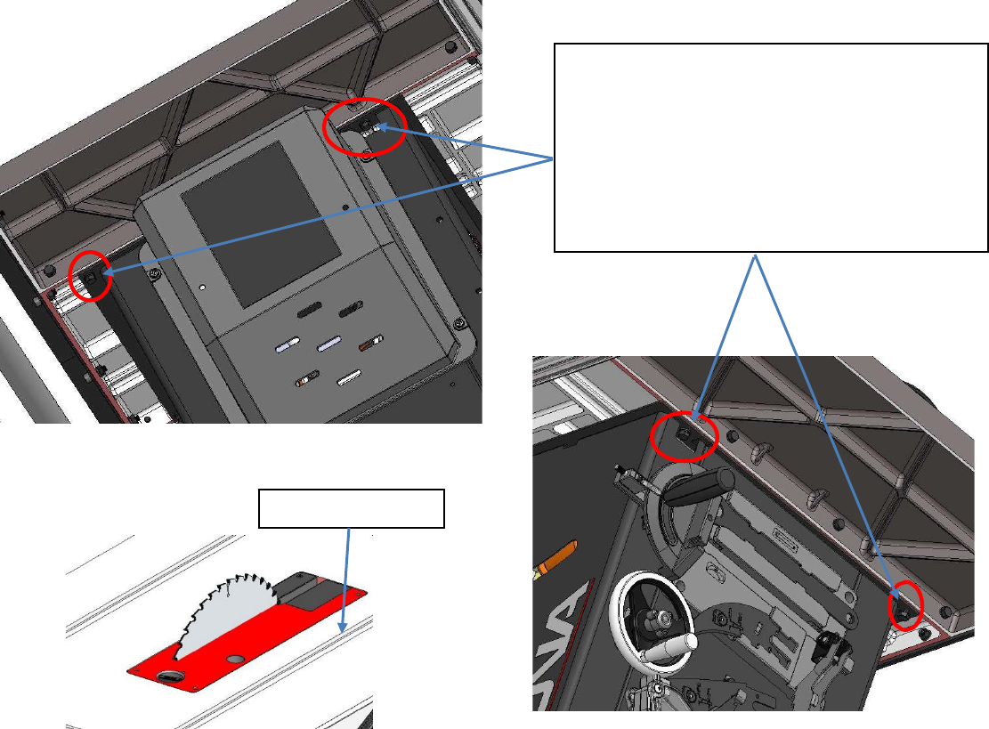
Fusion 3 Table Saw \ Maintenance \
46
© 2020 Laguna Tools
ALIGNING TABLE PARALLEL TO BLADE
Fig. F
Fig. G Fig. H
STEP 1: Loosen 4 bolts as shown.
STEP 2: Adjust table parallel to T-Slot (miter
slot), by pivoting table. Use a ruler to measure
from blade to T-Slot at the front and rear of
blade.
STEP 3: Tighten 4 bolts as shown.
T-Slot (Miter Slot)
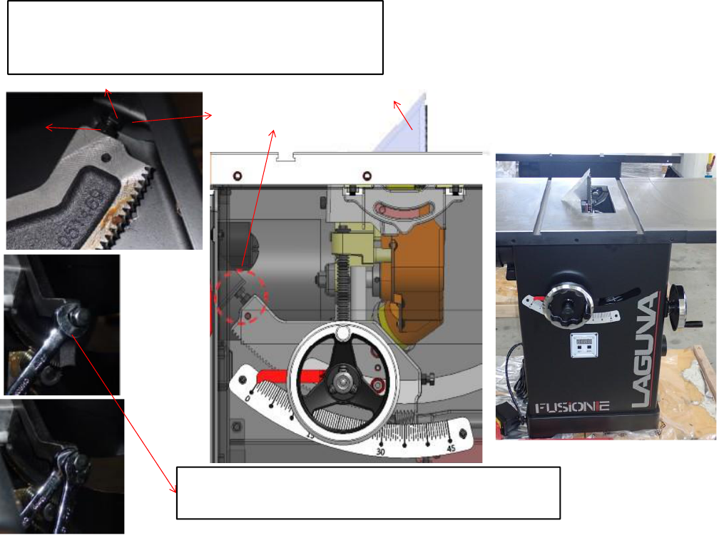
Fusion 3 Table Saw \ Troubleshooting \
© 2020 Laguna Tools
47
ADJUSTING 90º STOP

Fusion 3 Table Saw \ Maintenance \
48
© 2020 Laguna Tools
ADJUSTING 45º STOP
Fusion 3 Table Saw \ Troubleshooting \
© 2020 Laguna Tools
49
Maintenance
Unplug Machine prior
to any maintenance
work.
Allays unplug the machine
when changing the blade,
guards, or any maintenance.
General
Keep your machine clean. At the end of each day, clean the machine. Wood contains moisture, and if sawdust or wood
chips are not removed, they will cause rust. In general, we recommend that you only use a Teflon-based lubricant on the
saw. Regular oil attracts dust and dirt. Teflon lubricant tends to dry and has less of a tendency to accumulate dirt and saw
dust. Periodically check that all nuts and bolts are tight.
Drive belt
The drive belt should last for many years (depending on the usage) but needs to be inspected regularly for cracks, cuts and
general wear. If damage is found, replace the belt.
Bearings
All bearings are sealed for life and do not require any maintenance. If a bearing becomes faulty, replace it.
Rust
The saw is made from steel and cast iron. All non-painted surfaces will rust if not protected. It is recommended that they be
protected by applying wax or a Teflon- based lubricant to them.
Daily
Check:
Loose mounting bolts
Damaged saw blade
Damaged riving knifes, splitters, or blade guards
Worn or damaged wires
Any other unsafe condition
Monthly Maintenance:
Clean/vacuum dust buildup from inside cabinet and off
motors.
Check/replace belt for proper tension, damage or wear
Weekly
Maintenance:
Clean table surface and miter slot grooves
Clean and protect cast iron table
Clean rip fence
Every 6–12 Months:
Lubricate trunnion slides.
Lubricate worm gear.
Lubricate leadscrew.
Lubricate gearing and gearboxes.
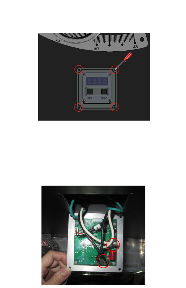
Fusion 3 Table Saw \ Maintenance \
50
© 2020 Laguna Tools
DRO POWER CONNECTION TEST/CHECK
If DRO does not power up or is inconsistent, please check the following:
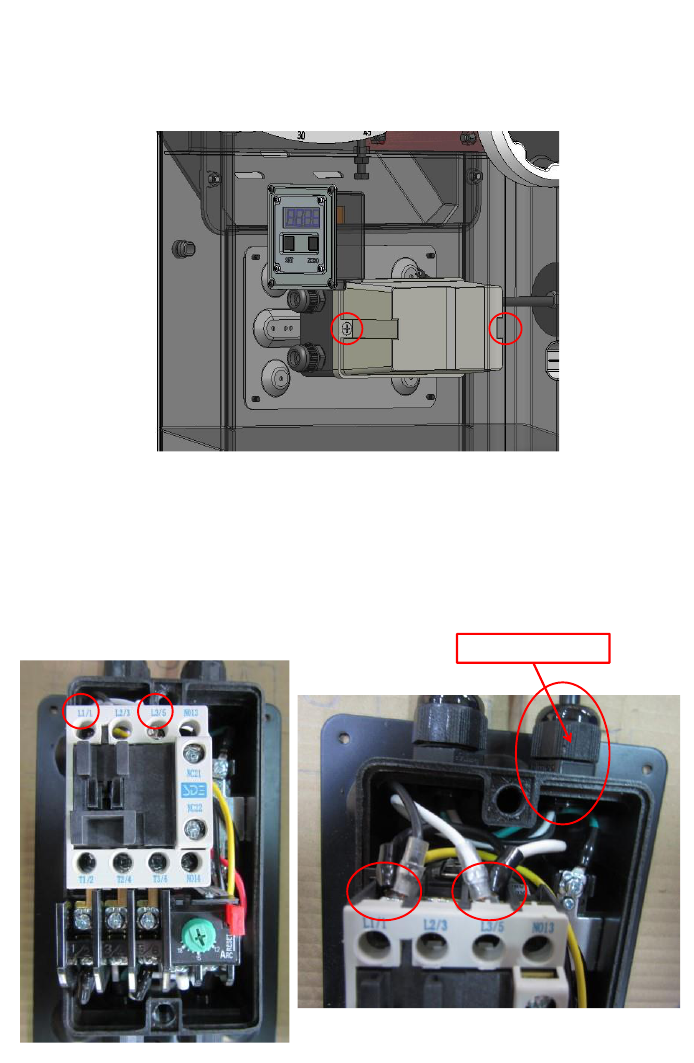
Fusion 3 Table Saw \ Troubleshooting \
© 2020 Laguna Tools
51

Fusion 3 Table Saw \ Maintenance \
52
© 2020 Laguna Tools
Troubleshooting
Behavior
Possible Causes
Solutions
Machine will not
start or
continues to trip
the breaker.
1.
Start capacitor at fault.
2.
Motor connection wired wrong.
3.
Wiring at fault.
4.
Motor Start/Stop switch at fault.
5.
Motor at fault.
6.
Run capacitor at fault.
7.
Wall circuit breaker tripped or at fault.
8.
Power supply switched OFF or at fault.
9.
Plug/receptacle at fault or wired incorrectly.
1.
Test/replace if faulty.
2.
Correct motor wiring connections.
3.
Check/fix broken, disconnected, or corroded
wires.
4. Replace
switch.
5.
Test/repair/replace.
6.
Test/replace if faulty.
7.
Ensure circuit size is correct/replace weak
breaker.
8.
Ensure power supply is on/has correct voltage.
9.
Test wires and contacts; correct the wiring.
Machine is
excessively loud
or is
experiencing
excessive
vibration.
1.
Motor or component loose.
2.
Blade at fault.
3.
Motor mount loose/broken.
4.
Machine incorrectly mounted.
5.
Arbor pulley loose.
6.
Belts worn or loose.
7.
Pulley loose or at fault.
8.
Arbor bearings at fault.
1.
Inspect/replace damaged
b
o
l
t
s
/
nu
t
s
,
and re
tighten with thread-locking fluid.
2.
Replace warped/bent blade; re-sharpen dull
blade.
3.
Tighten/replace.
4.
Tighten mounting
bolts; relocate/shim machine.
5.
Re-tighten/replace arbor pulley.
6.
Adjust tension of/replace belt.
7.
Realign/replace shaft, pulley, setscrew, and key.
8a. Replace arbor housing bearings; replace arbor.
8b. Test by rotating shaft; grinding/loose shaft
requires bearing replacement.
Machine trips
the overload, or
feels
underpowered
during operation.
1.
Feed rate/cutting speed too fast.
2.
Workpiece material unsuitable for machine.
3.
Pulley/sprocket slipping on shaft.
4.
Motor bearings at fault.
5.
Contactor (internal breaker) at fault.
6.
Motor overheated.
7.
Workpiece crooked; fence not aligned.
8.
Machine undersized for task; wrong blade.
9.
Run capacitor at fault.
10.
Belt is slipping from pulley.
11.
Motor wired incorrectly.
12.
Plug/receptacle at fault.
13.
Motor at fault.
1.
Decrease feed rate/cutting speed.
2.
Only cut wood; ensure moisture is below 20%.
3.
Test for good contacts/correct wiring.
4.
Replace loose pulley/shaft.
5.
Test/repair/replace.
6.
Test all legs for power/replace if faulty.
7.
Clean motor, let cool, and reduce workload.
8.
Straighten or replace workpiece; adjust fence.
9.
Use correct blade; reduce feed rate or depth of
cut.
10.
Test/repair/replace.
11.
Adjust tension of/replace belt.
12.
Wire motor correctly.
13.
Test/repair/replace.
Dust Collection
1.
Inadequate
suction
2.
No
suction
1.
Check Dust Collection Unit and hose fittings.
2.
move motor cover and verify that the internal
hose is fixed to the blade shroud port and the
external 4" port.

Fusion 3 Table Saw \ Specifications \
© 2020 Laguna Tools
53
Specifications
FUSION F1
FUSION F2
FUSION F3
FUSION F3 52
Maximum
Blade
Diameter
10" (254 mm)
10" (254 mm)
10" (254 mm)
10" (254 mm)
Max Rip Right of Blade
w/Included Fence & Rails
30” (762mm)
36” (914 mm)
36” (914 mm)
52” (1320 mm)
Fence
Type
Camlock T-Shape
w/Aluminum Face
Camlock T-Shape
w/European Hi-Lo Face
Camlock T-Shape
w/European Hi-Lo Face
Camlock T-Shape
w/European Hi-Lo Face
Table
Precision-Ground
Cast Iron
Precision-Ground Cast
Iron
Precision-Ground Cast Iron
Precision-Ground Cast
Iron
Wings
Pre-Formed Steel
Precision-Ground Cast
Iron
Precision-Ground Cast Iron
Precision-Ground Cast
Iron
Cabinet
Pre-Formed Steel
Pre-Formed Steel
14 Ga. Steel
14 Ga. Steel
Trunnions
Cast Alloy
Cast Alloy
Cast Iron
Cast Iron
Dust
Port
Size
4" (101 mm)
4" (101 mm)
4" (101 mm)
4" (101 mm)
Blade Guard Dust Port
Size
1-1/2" (38 mm)
1-1/2" in. (38 mm)
1-1/2" (38 mm)
1-1/2" (38 mm)
Weight,
Gross
214 lbs. (97 Kg)
359 lbs. (163 Kg)
496 lbs. (225 Kg)
523 lbs. (237 Kg)
Weight,
Net
195 lbs. (88.5 Kg)
276 lbs. (124.6 Kg)
396.8 lbs. (180 Kg)
422 lbs. (191 Kg)
Overall Width (side-to-
side)
59.5” (1513 mm)
66-7/8"(1699 mm)
69” (1753 mm)
85” (2159 mm)
Overall Depth (front-to-
back)
39-3/4” (1009 mm)
39-3/8" (1000 mm)
56" (1425 mm)
56" (1425 mm)
Overall
Height
46” (1168 mm)
47” (1193 mm)
47” (1193 mm)
47” (1193 mm)
Power
Requirement
110V/230V, Single-
Phase, 60 Hz (wired
110V)
110V/220V, Single-Phase,
60 Hz (wired 110V)
220V, Single-Phase, 60 Hz
220V, Single-Phase, 60 Hz
Horsepower
1.5HP
1.75HP
3HP
3HP
Country of Origin
Taiwan
Taiwan
Taiwan
Taiwan
Certified by a Nationally
Recognized Testing Laboratory
(NRTL)
Yes
Yes
Yes
Yes
FUSION F1
FUSION F2
FUSION F3
FUSION F3 52
Features
Fusion Hi-Lo Dust
Collection
Full Cabinet Body
Industrial 14 Gauge (2mm)
Cabinet
52" Rip Capacity
Fusion Over-Under
Trunnions
Cabinet Mounted Arbor
Accessory Tables (Outfeed
& Rip)
Industrial 14 Gauge (2mm)
Cabinet
Polished Cast Iron Table
Cast Iron Table & Wings
Industrial Fence Rail
Accessory Tables
(Outfeed & Rip)
Reset
Switch
European Hi-Lo Fence
Industrial Fusion Fence
Industrial Fence Rail
Quick-Release Blade Guard
and Spreader
Premium Zero Clearance
Throat Plate
Premium Electrical &
Hardware Components
Industrial Fusion Fence
Riving Knife Included
Fusion Hi-Lo Dust
Collection
Premium Miter Gauge
Premium Electrical &
Hardware Components
Push Stick included
Fusion Over-Under
Trunnions
Cast Iron Fusion Trunnions
Premium Miter Gauge
Miter Gauge Included
Reset
Switch
Cabinet Mounted Arbor
Cast Iron Fusion Trunnions

Fusion 3 Table Saw \ Specifications \
54
© 2020 Laguna Tools
Blade Changing Tool
Included
Quick-Release Blade Guard
and Spreader
Cast Iron Table & Wings
Cabinet Mounted Arbor
Integrated Tool Storage
Riving Knife Included
European Hi-Lo Fence
Cast Iron Table & Wings
Premium Handles
Push Stick included
Premium Zero Clearance
Throat Plate
European Hi-Lo Fence
Included 10 x 60T Carbide-
Tipped Blade
Miter Gauge Included
Fusion Hi-Lo Dust
Collection
Premium Zero Clearance
Throat Plate
Premium Arbor and Motor
Bearings
Blade Changing Tool
Included
Magnetic Contactor Switch
Fusion Hi-Lo Dust
Collection
Integrated Tool Storage
Quick-Release Blade Guard
and Spreader
Magnetic Contactor
Switch
Premium Handles
Riving Knife Included
Quick-Release Blade
Guard and Spreader
Included 10 x 60T Carbide-
Tipped Blade
Push Stick included
Riving Knife Included
Premium Arbor and Motor
Bearings
Miter Gauge Included
Push Stick included
Blade Changing Tool
Included
Miter Gauge Included
Integrated Tool Storage
Blade Changing Tool
Included
Included 10 x 60T Carbide-
Tipped Blade
Integrated Tool Storage
Premium Arbor and Motor
Bearings
Included 10 x 60T Carbide-
Tipped Blade
Premium Arbor and Motor
Bearings
FUSION F1
FUSION F2
FUSION F3
FUSION F3 52
Main Information
Table Saw Type
Hybrid
Cabinet
Cabinet
Cabinet
Cabinet
Maximum
Blade
Diameter
10 in. (254 mm)
10 in. (254 mm)
10 in. (254 mm)
10 in. (254 mm)
Arbor Size
5/8" (15.87 mm)
5/8" (15.87 mm)
5/8" (15.87 mm)
5/8" (15.87 mm)
Arbor
Speed
4000 RPM
4500 RPM
4500 RPM
4500 RPM
Maximum Width
of
Dado
3/4" (19.05 mm)
3/4" (19.05 mm)
3/4" (19.05 mm)
3/4" (19.05 mm)
Blade Tilt
Direction
Left
Left
Left
Left
Max Blade Tilt
45 deg.
45 Degrees
45 Degrees
45 Degrees
Maximum Depth of Cut
At 90 Degrees
3-1/8" (79.37 mm)
3-1/8" (79.37 mm)
3-1/8" (79.37 mm)
3-1/8" (79.37 mm)
Maximum Depth of Cut
At 45 Degrees
2-1/8" (53.97 mm)
2-1/8" (53.97 mm)
2-1/8" (53.97 mm)
2-1/8" (53.97 mm)
Max Rip Right of Blade
w/Included Fence & Rails
31" (787.4 mm)
37"(940
mm)
37" (940 mm)
53" (1346.2 mm)
Max Rip Left of Blade
w/Included Fence & Rails
19-5/8" (500 mm)
19-5/8" (500 mm)
19-5/8" (500 mm)
19-5/8" (500 mm)
FUSION F1
FUSION F2
FUSION F3
FUSION F3 52
Additional Blade
Information
Included Blade
10" x 60T
10" x 60T
10" x 60T
10" x 60T

Fusion 3 Table Saw \ Specifications \
© 2020 Laguna Tools
55
Riving Knife/Spreader
Thickness
3/32" (2.28 mm)
3/32" (2.28 mm)
3/32" (2.28 mm)
3/32" (2.28 mm)
Required Blade Body
Thickness
>3.0mm
>3.0mm
>3.0mm
>3.0mm
Required Blade Kerf
Thickness
<2.0mm
<2.0mm
<2.0mm
<2.0mm
FUSION F1
FUSION F2
FUSION F3
FUSION F3 52
Table
Information
Floor to Table Height
34-3/8" (873 mm)
34-7/8" (886.5 mm)
34-7/8" (886 mm)
34-7/8" (886 mm)
Table Size with Extension
Wings Width
44" (1118 mm)
44" (1118 mm)
60" (1547 mm)
76-7/8" (1953 mm)
Table Size with Extension
Wings Depth
27" (686 mm)
27" (686 mm)
30" (684 mm)
30" (684 mm)
Distance Front of Table
to Center of Blade
13-1/2" (342 mm)
13-3/8" (340 mm)
13-1/2" (342 mm)
13-1/2" (342 mm)
Distance Front of Table
to Blade At Maximum
Cut
8-5/8" (220 mm)
8-5/8" (220 mm)
8-5/8" (220 mm)
8-5/8" (220 mm)
Main Table Size
Thickness
1-1/2" (38 mm)
1-1/2" (38 mm)
1-1/2" (38 mm)
1-1/2" (38 mm)
FUSION F1
FUSION F2
FUSION F3
FUSION F3 52
Fence
Information
Fence
Type
Camlock T-Shape
w/Aluminum Face
Camlock T-Shape
w/European Hi-Lo Face
Camlock T-Shape
w/European Hi-Lo Face
Camlock T-Shape
w/European Hi-Lo Face
Fence Size Length
33-1/2" (850 mm)
33-1/2" (850 mm)
33-1/2" (850 mm)
33-1/2" (850 mm)
Fence Size Width
9-7/8" (250 mm)
9-7/8" (250 mm)
9-7/8" (250 mm)
9-7/8" (250 mm)
Fence Size Height
2-1/2" (62 mm)
3" (77 mm)
3" (77 mm)
3" (77 mm)
Fence Rail Type
Aluminum Extrusion/Angle
Steel
Aluminum Extrusion/Angle
Steel
Steel/Angle Steel
Steel/Angle Steel
Fence Rail Length
59-3/8" (1508 mm)
66-5/8"(1691 mm)
67-7/8" (1724 mm)
67-7/8" (1724 mm)
Fence Rail Width
2-7/8" (74.2 mm)
2-7/8" (74.2 mm)
3" (76.2 mm)
3" (76.2 mm)
Fence Rail Height
2" (50.8 mm)
2" (50.8 mm)
2" (50.8 mm)
2" (50.8 mm)
Miter
Gauge
Information
Miter Gauge Slot
Type
T-
Slot
T-
Slot
T-
Slot
T-
Slot
Miter Gauge Slot Size
Width
3/4" (19 mm)
3/4" (19 mm)
3/4" (19 mm)
3/4" (19 mm)
Miter Gauge Slot Size
Height
3/8" (9.8 mm)
3/8" (9.8 mm)
3/8" (9.8 mm)
3/8" (9.8 mm)
FUSION F1
FUSION F2
FUSION F3
FUSION F3 52
Construction
Table
Precision-Ground Cast Iron
Precision-Ground Cast Iron
Precision-Ground Cast Iron
Precision-Ground Cast Iron
Wings
Pre-Formed Steel
Precision-Ground Cast Iron
Precision-Ground Cast Iron
Precision-Ground Cast Iron
Cabinet
Pre-Formed Steel
Pre-Formed Steel
14 Ga. Steel
14 Ga. Steel

Fusion 3 Table Saw \ Specifications \
56
© 2020 Laguna Tools
Trunnions
Cast Alloy
Cast Alloy
Cast Iron
Cast Iron
Body Assembly
Pre-Formed Steel
Pre-Formed Steel
14 Ga. Steel
14 Ga. Steel
Fence
Assembly
Aluminum Extruded Body
Aluminum Extruded Body
Steel Body
Steel Body
Rails
Steel
Steel
Industrial Steel
Industrial Steel
Miter Gauge
Construction
Aluminum Body with Steel
Bar
Aluminum Body with Steel
Bar
Cast Iron with Steel Bar,
Aluminum Fence
Cast Iron with Steel Bar,
Aluminum Fence
Guard
Steel and Clear Plastic
Steel and Clear Plastic
Steel and Clear Plastic
Steel and Clear Plastic
Body/Cabinet Paint
Type/Finish
Powder
Coated
Powder
Coated
Powder
Coated
Powder
Coated
Arbor
Bearings
Sealed & Permanently
Lubricated
Sealed & Permanently
Lubricated
Sealed & Permanently
Lubricated
Sealed & Permanently
Lubricated
FUSION F1
FUSION F2
FUSION F3
FUSION F3 52
Other
Related Information
Number of Dust
Ports
1.00
1.00
1.00
1.00
Dust
Port
Size
4" (101.6 mm)
4" (101.6 mm)
4" (101.6 mm)
4" (101.6 mm)
Compatible
Mobile
Base
YES
Integrated
Integrated
Integrated
Blade Guard Dust Port
Size
1-1/2" (38.1 mm)
1-1/2" (38.1 mm)
1-1/2" (38.1 mm)
1-1/2" (38.1 mm)
Dust Collection CFM
Requirement (min.)
400 CFM
400 CFM
400 CFM
400 CFM
Dust Collection Static
Pressure
5" H20
5" H20
5" H20
5" H20
FUSION F1
FUSION F2
FUSION F3
FUSION F3 52
Product
Dimensions
Weight,
Gross
214 lbs. (97 Kg)
359 lbs. (163 Kg)
496 lbs. (225 Kg)
523 lbs. (237 Kg)
Weight,
Net
195 lbs. (88.5 Kg)
276 lbs. (124.6 Kg)
397 lbs. (180 Kg)
422 lbs. (191 Kg)
Overall Width (side-to-
side)
58-3/4"(1494 mm)
66-3/4" (1697 mm)
68-7/8" (1751 mm)
84-7/8" (2157.47 mm)
Overall Depth (front-to-
back)
37-1/4" (945 mm)
39-3/8" (1000 mm)
56-1/8" (1425 mm)
56-1/8" (1425 mm)
Overall
Height
42-1/2" (1080 mm)
42-7/8" (1090 mm)
42-7/8" (1090 mm)
42-7/8" (1090 mm)
Footprint
Width
20-1/2" (520.6 mm)
19-1/4" (490 mm)
20-1/2" (520 mm)
48" (1219.2 mm)
Footprint
Length
20-5/8" (525 mm)
18-5/8" (473 mm)
42-1/2" (1080 mm)
42-1/2" (1080 mm)
Space Required for Full
Range of Movement
Width (side-to-side)
58-3/4" (1494 mm)
66-3/4" (1697 mm)
68-7/8" (1751 mm)
85" (2157.47 mm)
Space Required for Full
Range of Movement
Depth (front-to-back)
37-1/4" (945 mm)
39-3/8" (1000 mm)
56-1/8" 1425 mm)
56-1/8" (1425 mm)
FUSION F1
FUSION F2
FUSION F3
FUSION F3 52
Shipping
Dimensions
Carton
Number
1.00
1.00
1.00
1.00
Carton
Type
Box
Wood
Crate
Wood
Crate
Wood
Crate
Content
Everything
Everything
Everything
Table
saw

Fusion 3 Table Saw \ Specifications \
© 2020 Laguna Tools
57
Weight,
Gross
214 Lbs (97 Kg)
359 lbs. (163 Kg)
482 lbs. (219 Kg)
482 lbs. (219 Kg)
Length
42-3/8" (1075 mm)
49-1/4" (1250 mm)
57" (1450 mm)
51-1/8" (1300 mm)
Width
26-3/4" (680 mm)
29-7/8" (760 mm)
29-7/8" (760 mm)
29-7/8" (760 mm)
Height
25-5/8" (650 mm)
42-3/4" (1085 mm)
42-3/4" (1085 mm)
42-3/4" (1085 mm)
Must Ship Upright
YES
YES
YES
YES
Carton
Number
2.00
Carton
Type
Wood
Crate
Content
52" Fence Rails
Weight,
Gross
51.58 lbs. (23.4 Kg)
Length
69-3/4" (1775 mm)
Width
4-1/8" (105 mm)
Height
3-7/8" (100 mm)
Must Ship Upright
YES
FUSION F1
FUSION F2
FUSION F3
FUSION F3 52
ELECTRICAL
Power
Requirement
110V, Single-Phase, 60 Hz
110V, Single-Phase, 60 Hz
220V, Single-Phase, 60 Hz
220V, Single-Phase, 60 Hz
Prewired
Voltage
110V
110V
220V
220V
Full-Load Current Rating
13A
14A
15A
15A
Minimum Circuit
Size
20A
20A
20A
20A
Connection
Type
Cord & Plug
Cord & Plug
Cord & Plug
Cord & Plug
Power Cord
Included
Yes
Yes
Yes
Yes
Power Cord
Length
6 ft.
6 ft.
6 ft.
6 ft.
Power Cord
Gauge
14 AWG
14 AWG
14 AWG
14 AWG
Plug Included
Yes
Yes
Yes
Yes
Switch
Type
ON/OFF Push Button
Switch w/Large Shut-Off
Paddle & Padlock
ON/OFF Push Button
Switch w/Large Shut-Off
Paddle & Padlock
ON/OFF Push Button
Switch w/Large Shut-Off
Paddle & Padlock,
Additional Magnetic
Contactor in line
ON/OFF Push Button
Switch w/Large Shut-Off
Paddle & Padlock,
Additional Magnetic
Contactor in line
FUSION F1
FUSION F2
FUSION F3
FUSION F3 52
MOTOR
Use
Main
Main
Main
Main
Horsepower
1.5HP
1.75HP
3HP
3HP
Phase
Single-
Phase
Single-
Phase
Single-
Phase
Single-
Phase
Amps
13A
14A
15A
(220V)
15A
(220V)
Speed
3600 RPM
3450 RPM
3450 RPM
3450 RPM
Type
TEFC Capacitor-Start
Induction
TEFC Capacitor-Start
Induction
TEFC Capacitor-Start
Induction
TEFC Capacitor-Start
Induction
Power Transfer
Poly-V Belt Drive
Poly-V Belt Drive
Poly-V Belt Drive
Poly-V Belt Drive
Bearings
Sealed & Permanently
Lubricated
Sealed & Permanently
Lubricated
Sealed & Permanently
Lubricated
Sealed & Permanently
Lubricated

Fusion 3 Table Saw \ Specifications \
58
© 2020 Laguna Tools
FUSION F1
FUSION F2
FUSION F3
FUSION F3 52
OTHER
SPECIFICATIONS
Country of Origin
Taiwan
Taiwan
Taiwan
Taiwan
Warranty
1 Year
1 Year
1 Year
1 Year
Approximate Assembly &
Setup Time
1 Hour
1 Hour
1 Hour
1 Hour
Serial Number Location
ID label on cabinet
ID label on cabinet
ID label on cabinet
ID label on cabinet
Sound Rating
60-78 dB
60-78 dB
60-78 dB
60-78 dB
ISO 9001 Factory
Yes
Yes
Yes
Yes
Certified by a Nationally
Recognized Testing
Laboratory (NRTL)
Yes
Yes
Yes
Yes
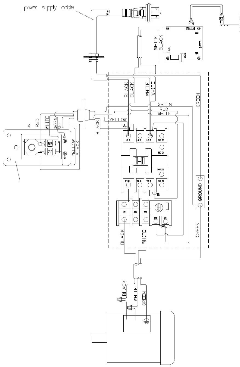
Fusion 3 Table Saw
\
Replacement Parts Diagram \
© 2020 Laguna Tools
59
Wiring
Diagram
Switch Plate
DRO
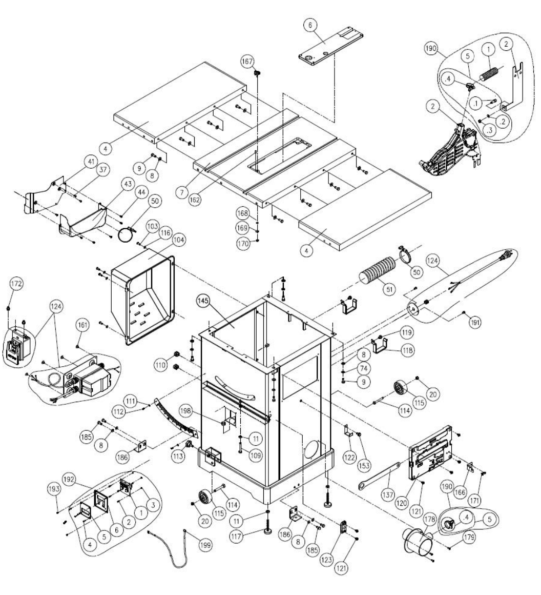
Fusion 3 Table Saw \ Wiring Diagram \
60
© 2020 Laguna Tools
Replacement
Parts
Diagram
Cabinet
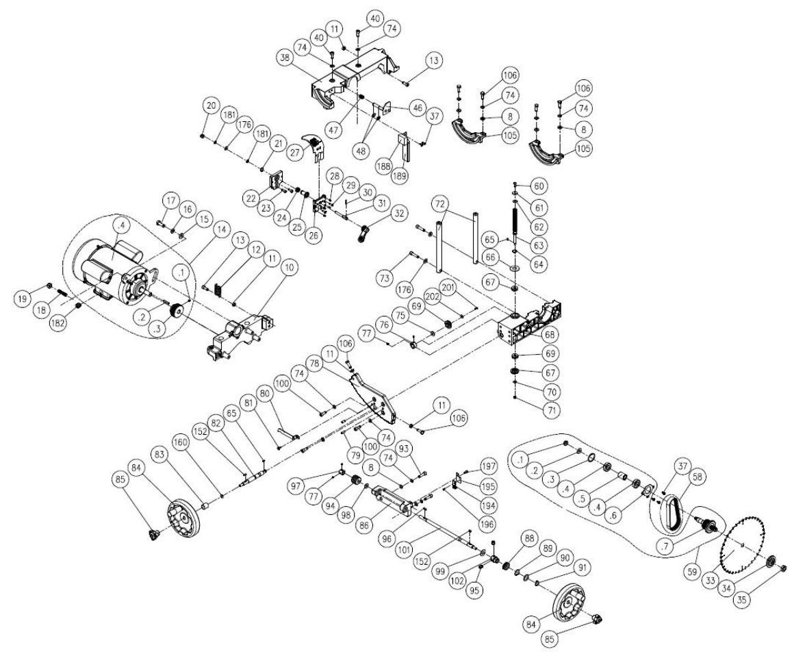
Fusion 3 Table Saw
\
Replacement Parts Diagram \
© 2020 Laguna Tools
61
Internal
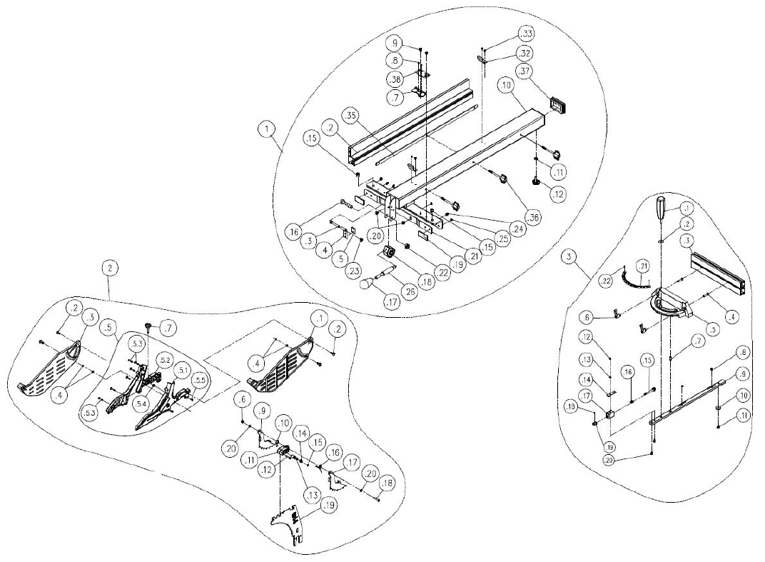
Fusion 3 Table Saw
\
Replacement Parts Diagram \
62
© 2020 Laguna Tools
Blade
Guard
&
Miter
Gauge
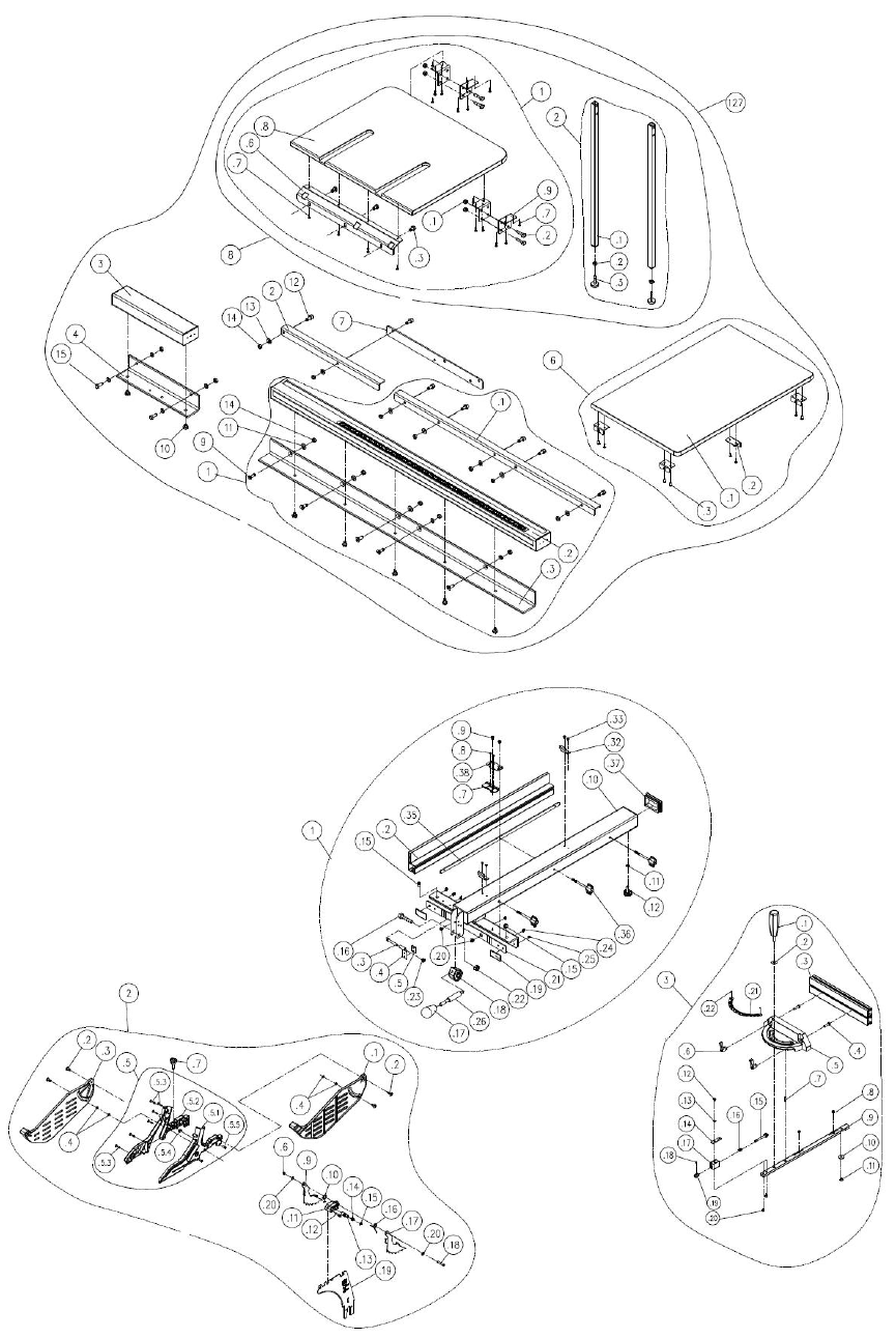
Fusion 3 Table Saw
\
Replacement Parts Diagram \
© 2020 Laguna Tools
63
36" Rails, Fence, Guard & Outfeed Table
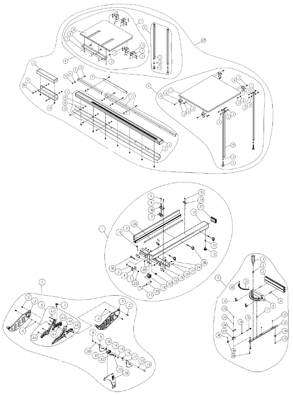
Fusion 3 Table Saw
\
Replacement Parts Diagram \
64
© 2020 Laguna Tools
52" Rails, Fence, Guard & Outfeed Table

© 2020 Laguna Tools
65
Parts
List
Key
Part No.
Description
Specifications
Qty
1
925199-000
Fence Assembly
L\H (800mm)
1
.2
310587-909
Adaptor
800mm
1
.3
000002-308
Hex Screw
M6-1.0x45
1
.4
171993-904
Bracket
1
.5
250602-621
Frictional Plate
1
.7
251456-620
Pointer
(L\H)
1
.8
001101-205
Pan Head Tapping Screw
M3-1.06x6
2
.9
000304-210
Pan Head Screw
M6-1.0x6
2
.10
174903-308
Fence Body
1
.11
008005-100
Hex Nut
M6-1.0 (10Bx5H)
1
.12
250587-615
Frictional Wheel
1
.15
250472-621
Plastic Set Screw
M12-1.75
2
.16
000004-306
Hex Screw
M10-1.5x50
1
.17
230282-615
Ball
1
.18
922141-000
Compress Cam Assembly
1
.19
250471-621
Frictional Plate
2
.20
002103-103
Flat Head Screw
M6-1.0x8
2
.21
171372-904
Bracket for Frictional Plate
1
.22
008308-100
Lock Nut
M10-1P (17Bx12H)
1
.23
008304-100
Lock Nut
M6-1.0 (10Bx6H)
1
.24
001903-105
SET Lock Screw
M8-1.25x8
2
.25
250672-615
Spacer
4
.26
380883-901
Handle Shaft
1
.32
270007-901
Spring Plate
2
.33
000302-101
Pan Head Screw
M4-0.7x6
4
.35
174713-000
Fix Plate
1
.36
251433-615
Wing Screw
3
.37
250624-615
End Cap
1
.38
175051-905
Pointer Bracket
1
2
924883-000
Blade Guard Assembly
1
Key
Part No.
Description
Specifications
Qty
.1
251246-000
Right Cover
1
.2
290073-905
Shoulder Shaft
4
.3
251247-000
Left Cover
1
.4
043317-000
O-Ring
P006
4

Fusion 3 Table Saw
\ Replacement Parts Table \
66
© 2020 Laguna Tools
.5
924884-000
Blade Guard support Assembly
1
.5.1
924885-000
Support (L)
1
.5.2
924886-000
Support (R)
1
.5.3
001201-002
Tapping Screw
M4-1.41x20
6
.5.4
008005-200
Hex Nut
M6-1.0P (10Bx5H)
1
.5.5
360960-901
Pin
2
.6
008302-100
Lock Nut
M5-0.8 (8Bx6H)
1
.7
230336-615
Bolt
1
.9
171378-904
Anti-Kick Finger -Left
1
.10
280162-901
Spring
1
.11
251311-615
Block
1
.12
360864-000
Pin
1
.13
360865-901
Spreader Shaft
1
.14
280160-901
Spring
1
.15
010204-000
Retaining Ring
ETW-7
1
.16
280163-901
Spring
1
.17
171379-904
Anti-Kick Finger -Right
1
.18
000303-110
Pan Head Screw
M5-0.8x30
1
.19
174397-904
Spreader
1
.20
006001-012
Flat Washer
5.3x12x1.0
2
3
924562-000
Miter Gauge Assy
1
.1
230191-000
Handle
1
.2
006002-056
Flat Washer
8.5x23x2
1
.3
310500-911
Apron
1
.4
003001-102
Hex Screw
1/4"-20x1"
2
.5
090342-008
Miter Gauge Body
1
.6
230408-000
Lock Handle
2
.7
360355-901
Pin
1
.8
000204-114
SET Screw
M8-1.25x6
2
.9
381390-904
Slot Bar
1
Key
Part No.
Description
Specifications
Qty
.10
130380-903
Washer
1
.11
000403-209
Flat Head Phillip Screw
M6-1.0x8
1
.12
000303-202
Pan Head Screw
M5-0.8x8
1
.13
006002-009
Flat Washer
5.2-10x1.0
1
.14
251305-620
Pointer
1
.15
924563-000
Adjusting Wheel Assembly
1
.16
280272-000
Spring
1
.17
130378-903
Spacer
1
.18
000201-105
SET Screw
M4-0.7x4
1
.19
381388-904
Handle
1

© 2020 Laguna Tools
67
.20
000102-102
Cap Screw
M5-0.8x8
2
.21
574852-000
Scale
1
.22
002301-201
Rivet
2x5
2
4
051386-000
Extension Table
2
6
924397-000
Table Insert Assembly
1
7
051368-000
Table
1
8
006001-049
Flat Washer
8.5-16x2.0
22
9
000003-104
Hex Screw
M8-1.25x20
12
10
051370-000
Up-down Bracket
1
11
008006-100
Hex Nut
M8-1.25 (13x6.5)
7
12
280258-905
Spring
1
13
000104-106
Cap Screw
M8-1.25x20
2
14
901081-000
Motor Assy
3HP/230V/60HZ/1PH/2P
1
15
006001-069
Flat Washer
10x20x3.0
1
16
006307-100
Spring Washer
10.2-18.5
1
17
000004-103
Hex Screw
M10-1.5x30
1
18
360863-901
Motor Fixing Shaft
1
19
008308-100
Lock Nut
M10-1.5 (17Bx12H)
1
20
008306-100
Lock Nut
M8-1.25 (13Bx9H)
3
21
010005-000
Retaining Ring
STW-14
1
22
130359-903
Bracket for Riving Knife
1
23
000104-104
Cap Screw
M8-1.25x16
2
24
280259-901
Spring
1
25
130363-903
Bushing
1
Key
Part No.
Description
Specifications
Qty
26
110073-000
Bracket for Riving Knife
1
27
174396-904
Riving Knife
1
28
001902-710
SET Lock Screw
M6-1.0x8
4
29
000804-106
Round Head Screw
M5-0.8x16
2
30
361251-905
Pin
1
31
361250-901
Fixing Knob
1
32
110071-000
Lock Handle
1
33
390017-000
Sawblade
10''/40T
1
34
174399-901
Sawblade clamp
1
35
380205-901
Nut
TW5/8"-12
1
37
002503-101
Round Head Socket Lock Screw
M5-0.8x12
8
38
051369-000
Upper Trunnion
1
40
002601-107
Locking CAP screw
M8-1.25x25
2
41
174773-000
Fixing Plate
1

Fusion 3 Table Saw
\ Replacement Parts Table \
68
© 2020 Laguna Tools
43
251398-615
Dust Hood
1
44
002002-101
Round Head Phillip Screw
M5-0.8x8
5
46
174325-156
Arbor Lock Handle
1
47
280260-901
Spring
1
48
010206-000
Retaining Ring
2
50
042608-000
Clamp
60-80mm (I.D.)
2
51
042620-008
Dust Hose
2.5” (I.D.) 800mm
1
58
014354-000
Poly-V-Belt
135J-7
1
59
925157-000
Arbor Assembly
1
.1
008316-200
Lock Nut
M10-1.5 (17Bx8H)
1
.2
006001-075
Flat Washer
10.3x22x2.0
1
.3
010103-000
Retaining Ring
RTW-35
1
.4
030211-002
Ball Bearing
6003
2
.5
190270-901
Spacer
1
.6
174305-901
Fixed Plate
1
.7
381281-902
Arbor
1
60
000002-103
Hex Screw
M6-1.0x16
1
61
006001-020
Flat Washer
6.2x20x3.0
1
Key
Part No.
Description
Specifications
Qty
62
006007-114
Flat Washer
6.4x16x1.6
1
63
361245-901
Lead Screw
1
64
010007-000
Retaining Ring
STW-16
1
65
012002-003
Key
4x4x8
2
66
174324-000
Washer
1
67
031011-001
Bearing
51100
2
68
090324-000
#N/A
1
69
381474-000
Bevel Gear
1
70
006001-025
Flat Washer
6.4x16x1.0
1
71
008317-300
Lock Nut
M6-1.0 (10Bx5H)
2
72
361246-000
Column
2
73
002601-108
Locking CAP screw
M8-1.25x35
2
74
006305-100
Spring Washer
8.2x15.4
15
75
006001-078
Flat Washer
10.5x19x1.5
1
76
190273-901
Bushing
1
77
000202-101
SET Screw
M5-0.8x5
4
78
051469-000
#N/A
1
79
011004-103
Spring Pin
6x25
2
80
175012-156
Pointer
1
81
002402-101
Round Head Lock Screw
w/Washer
M5-0.8x12/5x10.5x1.0
1

© 2020 Laguna Tools
69
82
361429-901
Shaft
1
83
251455-615
Bushing
1
84
924505-000
Handwheel Assembly
2
84
240090-000
Handwheel
1
84
230284-000
Folding Handle
1
84
000403-103
Flat Head Phillip Screw
M6-1.0x12
1
85
920703-000
Fixing Knob
2
86
051470-000
Worm Bracket
1
88
660229-000
Magnetic Ring
1
89
006706-100
Wave Washer
WW-18
1
90
006001-203
Flat Washer
18-28x1
1
91
010009-000
Retaining Ring
STW-18
1
93
000104-110
Cap Screw
M8-1.25x30
2
Key
Part No.
Description
Specifications
Qty
94
360709-901
Worm Shaft
1
95
001902-109
SET Lock Screw
M6-1.0x6
2
96
012002-006
Key
4x4x16
1
97
130126-903
Lock Ring
1
98
006006-120
Flat Washer
20x10.2±0.1x2±0.1
1
99
006004-167
Flat Washer
13x28x0.8
1
100
000104-108
Cap Screw
M8-1.25x25
3
101
361428-901
Shaft
1
102
381463-901
Bushing
1
103
000304-107
Pan Head Screw
M6-1.0x16
4
104
251239-615
Motor Cover
1
105
051135-000
Trunnion Support
2
106
000003-105
Hex Screw
M8-1.25x25
6
109
000003-115
Hex Screw
M8-1.25x55
1
110
020003-000
Strain Relief
SB7R-3
1
111
006001-001
Flat Washer
4.3x10x1.0
2
112
000302-102
Pan Head Screw
M4-0.7x8
2
113
004001-101
Knob
5/16"-18x3/4"
2
114
000003-316
Hex Screw
M8-1.25x60
2
115
250399-615
Wheel
2
116
006001-022
Flat Washer
6.3x13x1.0
4
117
230041-000
Leveling foot
2
118
170541-904
Slide Shelf
2
119
049201-101
Hex Screw w/Flat Washer
M8-1.25x16 (13Bx6.5H)
2
120
251251-615
Storage Box
1

Fusion 3 Table Saw
\ Replacement Parts Table \
70
© 2020 Laguna Tools
121
001603-102
Round Head Screw w/Washer
M6-1.0x10/6x13.2x1.0
6
122
170965-904
Fix Plate
1
123
250407-615
Worm Shaft Bracket
1
124
938085-000
Magnetic Switch Assy
3HP
1
127A
924914-000
36" Rail. Right Table. Rear Table
Assembly
1
1
924915-000
36" Rail Assembly
36"
1
.1
924923-000
Rear Rail
36"
1
Key
Part No.
Description
Specifications
Qty
.2
924916-000
Front Rail Assembly
36"
1
.3
924917-000
Front Rail Bracket
36"
1
2
924783-000
Rear Rail (L)
1
3
924768-000
Front Rail (L)
1
4
924772-000
Front Rail Bracket (L)
1
6
924773-000
Right Table Assembly
1
.1
440098-000
Right Table
1
.2
173139-902
Brace
4
.3
230086-901
Tapping Screw
8
7
924969-901
Connect Plate
1
8
924796-000
Rear Table Leg Assembly
1
.1
924797-000
Rear Table Leg Assembly
1
.1
008308-100
Lock Nut
M10-1.5 (17Bx12H)
4
.2
000004-112
Hex Screw
M10-1.5x45
4
.3
049201-101
Hex Screw w/Flat Washer
M8-1.25x16 (13Bx6.5H)
3
.5
174780-308
Support Plate
1
.6
001102-505
Round Hear Tapping Screw
M4-1.59x16
16
.7
440099-000
Rear Table
1
.8
171301-904
Fixed Plate
4
.2
924798-000
Leg Assembly
1
.1
190208-365
Leg
2
.2
008006-100
Hex Nut
M8-1.25 (13Bx6.5H)
2
.3
230041-000
Leveling foot
S20C+NBR
2
9
000704-102
Flat Head Hex. Screw
M8-1.25x25
5
10
049201-102
Hex Screw w/Flat Washer
M8-1.25x12 (13Bx5.5H)
7
11
006305-100
Spring Washer
8.2x15.4
3
12
001803-103
CAP Screw w/ Spring Washer
M8-1.25x25/8.2x13.7
7
13
006001-049
Flat Washer
8.5x16x2.0
16
14
008006-100
Hex Nut
M8-1.25 (13Bx6.5H)
14
15
000003-105
Hex Screw
M8-1.25x25
2
127B
924970-000
52" Rail. Right Table. Rear Table
1

© 2020 Laguna Tools
71
Assembly
Key
Part No.
Description
Specifications
Qty
1
924971-000
52" Rail. Right Table. Rear Table
Assembly
52"
1
.1
924924-000
Rear Rail
52"
1
.2
924920-000
Front Rail Assembly
52"
1
.3
924921-000
Front Rail Bracket
52"
1
2
924783-000
Rear Rail (L)
1
3
924768-000
Front Rail (L)
1
4
924772-000
Front Rail Bracket (L)
1
6
924809-000
Right Table Assembly
1
.1
001803-102
CAP Screw w/ Spring Washer
M8-1.25x20/8.2x15.4
4
.2
006001-049
Flat Washer
8.5x16x2.0
8
.3
008006-100
Hex Nut
M8-1.25 (13Bx6.5H)
10
.4
000704-102
Flat Head Hex Screw
M8-1.25x25
4
.5
230041-000
Leveling foot
2
.7
440077-000
Right Table
1
.8
173139-902
Brace
4
.9
230086-901
Tapping Screw
8
.10
190205-308
Leg
2
7
924969-000
Connect Plate
1
8
924796-000
Rear Table Leg Assembly
1
.1
924797-000
Rear Table Leg Assembly
1
.1
008308-100
Lock Nut
M10-1.5 (17Bx12H)
4
.2
000004-112
Hex Screw
M10-1.5x45
4
.3
049201-101
Hex Screw w/Flat Washer
M8-1.25x16 (13Bx6.5H)
3
.5
174780-308
Support Plate
1
.6
001102-505
Round Hear Tapping Screw
M4-1.59x16
16
.7
440099-000
Rear Table
1
.8
171301-904
Fixed Plate
4
.2
924798-000
Leg Assembly
1
.1
190208-365
Leg
2
.2
008006-100
Hex Nut
M8-1.25 (13Bx6.5H)
2
.3
230041-000
Leveling foot
S20C+NBR
2
10
000704-102
Flat Head Hex Screw
M8-1.25x25
3
Key
Part No.
Description
Specifications
Qty

Fusion 3 Table Saw
\ Replacement Parts Table \
72
© 2020 Laguna Tools
11
049201-102
Hex Screw w/Flat Washer
M8-1.25x12/(13Bx5.5H)
9
12
006305-100
Spring Washer
8.2x15.4
3
13
001803-103
CAP Screw w/ Spring Washer
M8-1.25Px25/8.2x13.7
5
14
006001-049
Flat Washer
8.5-16x2.0
9
15
008006-100
Hex Nut
M8-1.25 (13Bx6.5H)
10
16
000003-105
Hex Screw
M8-1.25x25
2
130
251362-615
Push Sticks
1
133
040002-000
Hex Wrench
2.5 mm
1
134
040006-000
Hex Wrench
6 mm
1
135
174569-904
Open Wrench
10/13 mm
1
137
174315-904
Arbor Wrench
1
145
175013-000
Stand
1
152
012002-005
Key
4x4x12
2
153
049201-101
Hex Screw w/Flat Washer
M8-1.25x16/(13Bx6.5H)
1
160
043322-000
O-Ring
P11
1
161
002402-102
Round Head Lock Screw
w/Washer
M5-0.8x10-5x16x1.5
4
162
011001-103
Spring Pin
3x10
1
166
174398-904
Hook
1
167
251243-615
Knob
1
168
006701-100
Wave Washer
WW-6
1
169
006001-137
Flat Washer
5.3x16x1.5
1
170
008302-100
Lock Nut
M5-0.8 (8Bx6H)
1
171
001104-703
Round Hear Tapping Screw
M5-2.12x12
2
172
049201-102
Hex Screw w/Flat Washer
M8-1.25x12/(13Bx5.5H)
2
173
040013-000
Hex Wrench
5 mm
1
176
006001-045
Flat Washer
8.5x16x1.0
3
178
251418-615
Hose Adapter
1
179
000303-104
Pan Head Screw
M5-0.8x12
3
181
006702-100
Wave Washer
WW-8
2
185
000003-102
Hex Screw
M8-1.25x16
4
Key
Part No.
Description
Specifications
Qty
186
174711-000
Fix Plate
2
189
174772-000
Plate
1
190A
924854-000
Over Head Guards Assembly
36"
1
1
042620-015
Dust Hose
1.5 / 2700mm (I.D.)
1
2
174887-904
Brace
1

© 2020 Laguna Tools
73
5
850913-000
Hardware Bag for 36" Over-
Head Guards
1
.1
001803-103
CAP Screw w/ Spring Washer
M8-1.25x25/8.2x13.7
1
.2
006001-049
Flat Washer
8.5x16x2.0
1
.3
008006-100
Hex Nut
M8-1.25 (13Bx6.5H)
1
.4
042622-003
Clamp
30-45 mm (I.D.)
2
190B
924855-000
Over Head Guards Assembly
52"
1
1
042620-016
Dust Hose
1.5 / 3700mm (I.D.)
1
2
174887-904
Brace
1
5
850913-000
Hardware Bag for 52" Over
Head Guards
1
.1
042622-003
Clamp
30-45 mm (I.D.)
2
.2
001803-103
CAP Screw w/ Spring Washer
M8-1.25x25/8.2x13.7
1
.3
006001-049
Flat Washer
8.5x16x2.0
1
.4
008006-100
Hex Nut
M8-1.25 (13Bx6.5H)
1
191
000304-102
Pan Head Screw
M6-1.0x10
2
192
950848-000
Tilt DRO Assembly
1
193
000805-101
Round Head Screw
M4-0.7x6
4
194
491221-000
Plate
1
195
175025-000
Fixed Plate
1
196
000301-201
Pan Head Screw
M3-0.5x6
1
197
000102-103
Cap Screw
M5-0.8x10
1
198
021808-000
Wire Clamp
NB-1419
1
199
474048-018
Cord
24AWG/4C/550mm
1
201
002504-701
Round Head Socket Lock Screw
M4-0.7x10
1
202
006003-199
Flat Washer
4.3x14x2.0
1
203
381479-000
Bevel Gear
1
NOTES:
Fusion 3 Table Saw \ Warranty \
74
© 2020 Laguna Tools
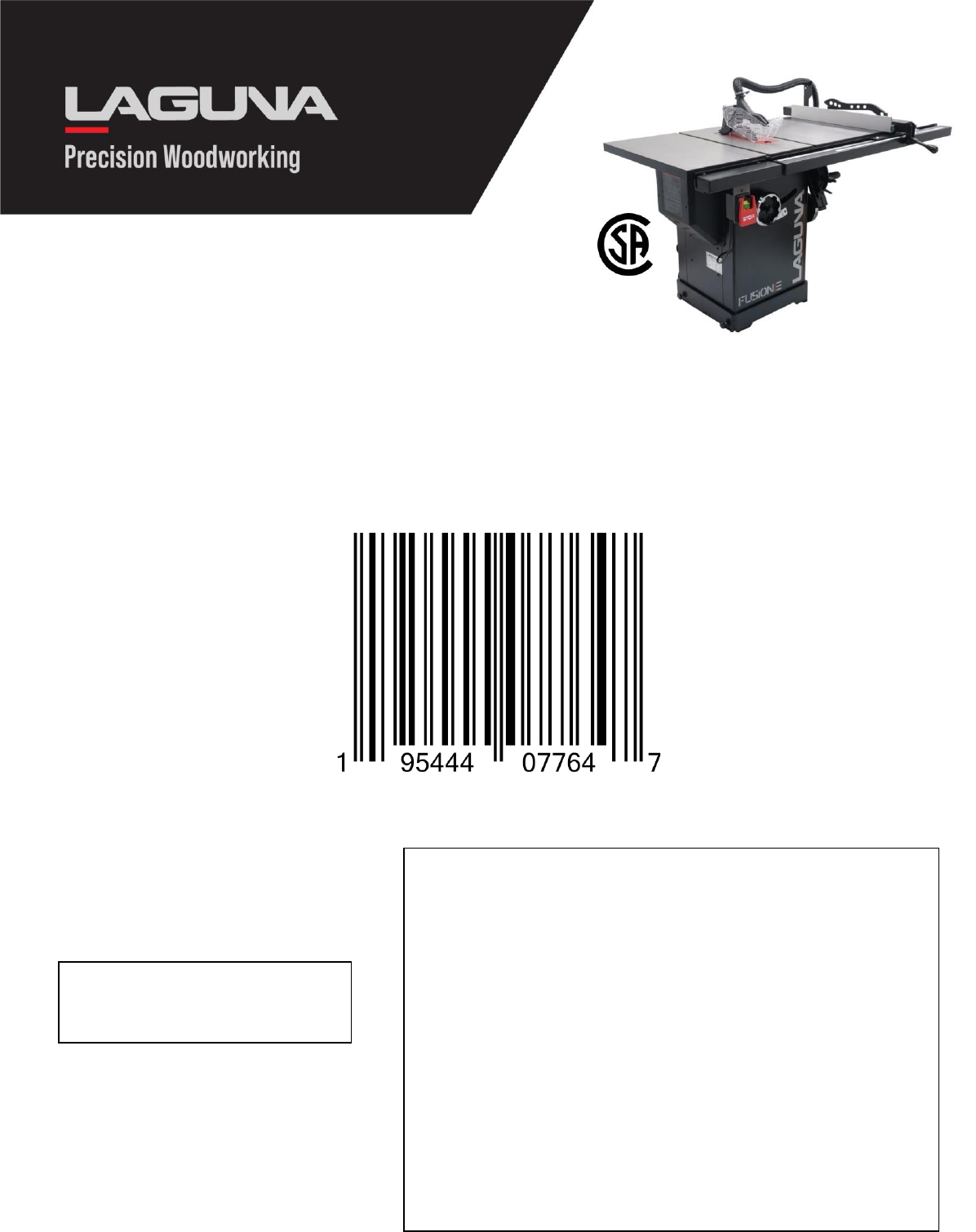
Fusion
3
Table
Saw
175370
230V/1PH/60Hz
w/
3HP,
36"
RIP
MTSF3362203-0130-36
NET WEIGHT: 397 lbs.
GROSS WEIGHT: 496 lbs.
BOX
NUMBER
SERIAL
NUMBER
READ
BEFORE
SIGNING
CUSTOMER
RESPONSIBILITIES
Note any carton shortages on the carrier’s shipping documents.
Note all damages on the carrier’s shipping documents.
Note any missing or broken packaging on the carriers shipping
documents.
All product shortage claims must be made to Laguna Tools within 2
days from the shipping date; otherwise claim cannot be honored.
CARRIER
RESPONSIBILITIES
Do not break down skid
Do not remove any part of packaging
Notify Consignee of any damage
Carrier will be 100% liable for any damage.
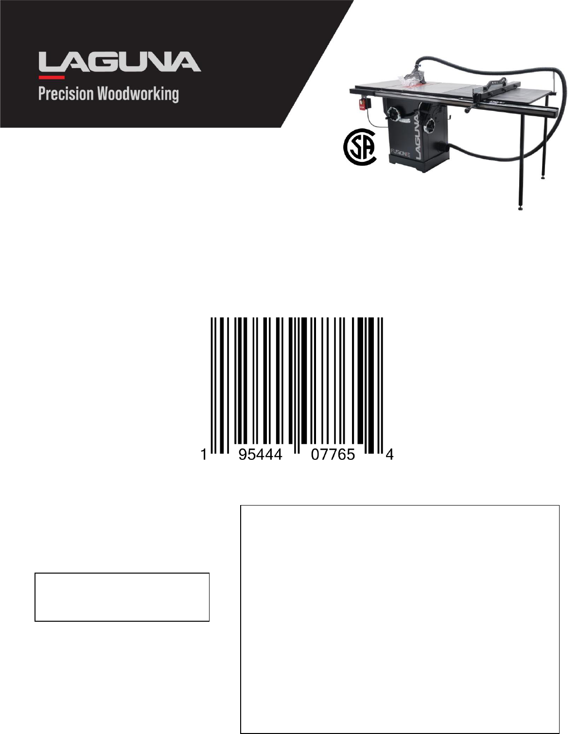
Fusion
3
Table
Saw
52"
175370
230V/1PH/60Hz
w/
3HP,
52"
RIP
MTSF3362203-0130-52
NET WEIGHT: 422 lbs.
GROSS WEIGHT: 523 lbs.
BOX
NUMBER
SERIAL
NUMBER
READ
BEFORE
SIGNING
CUSTOMER
RESPONSIBILITIES
Note any carton shortages on the carrier’s shipping documents.
Note all damages on the carrier’s shipping documents.
Note any missing or broken packaging on the carriers shipping
documents.
All product shortage claims must be made to Laguna Tools within 2
days from the shipping date; otherwise claim cannot be honored.
CARRIER
RESPONSIBILITIES
Do not break down skid
Do not remove any part of packaging
Notify Consignee of any damage
Carrier will be 100% liable for any damage.

LAGUNA
AMERICAN
HEADQUARTERS
Texas: 744 Refuge Way Suite 200, Grand Prairie, Texas 75050, U.S.A. Phone: +1-800-332-4094
Huntington Beach: 7291 Heil Ave Huntington Beach, CA 92647, U.S.A. Phone: +1-949-474-1200
South Carolina: 825 Bistline Dr. Ste 101, West Columbia, SC 29172, U.S.A. Phone: +1-800-234-1976
Minnesota: 5250 West 74th St, Edina, MN 55439, U.S.A Phone: +1-949-474-1200
LAGUNA
EUROPE
Walker Rd, Bardon Hill, Coalville LE67 1TU, United Kingdom. Phone: +44-1530-516921
DAKE
CORPORATION
724 Robbins Road, Grand Haven, MI 49417, United States +1-800-937-3253
© 2020 Laguna Tools 021023
